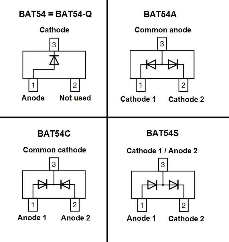
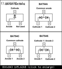
Diodes BAT54 series are a Schottky diodes available at four different configurations - depending on the ending letter. The diode BAT54 (or BAT54-Q) is a single diode in a 3-pin package (one of the pins is not used) while all other configurations -A, -C or -S are double diodes combined in a single package:
Regarding the testing, you can use a multimeter at the diode test range. If it is a double configuration diode, test each of the diodes separately:
1) Testing the diode in the forward direction:Connect the positive (red probe) of the multimeter to the Anode pin, and the negative (black probe) of the multimeter to the Cathode pin of the diode. The multimeter should show a voltage drop of about 0,25V.
2) Testing the diode in the reverse direction:Now reverse the polarity of the test leads (red probe of the multimeter to the Cathode pin, and the black probe to the Anode pin of the diode). In this case the multimeter should not detect anything - it should display "1." or "OL" (Over Load) depending on the multimeter.
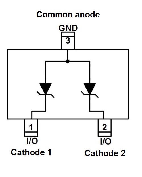
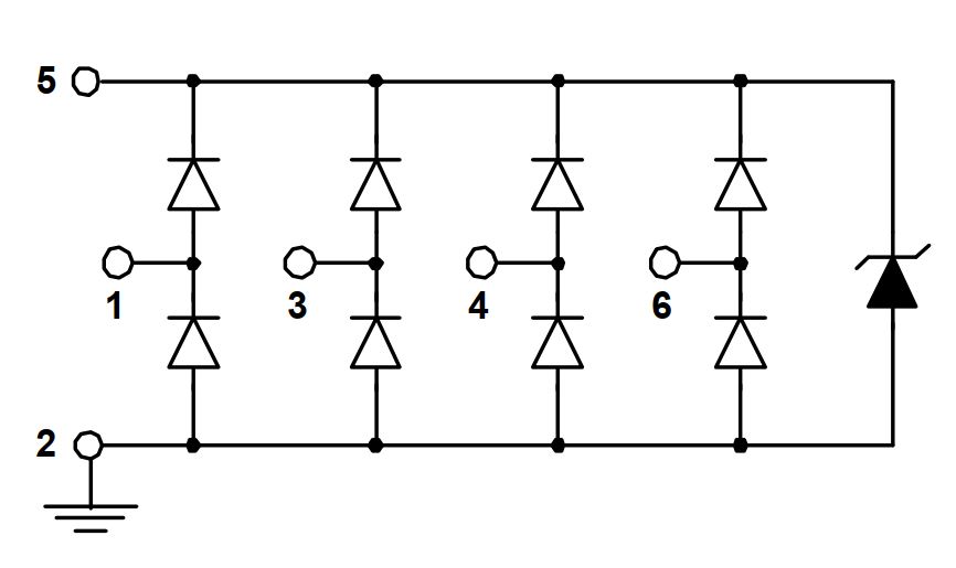
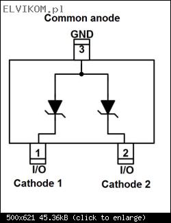
Diode AZ4024-02S is a double Suppressor (ESD, TVS) diodes combined in a single package:
Regarding the testing, you can't test this type of diodes with just a multimeter. Perform both tests on each of the built-in diodes.
1) Testing the diode in the forward direction:Use a multimeter at the diode test range.
Connect the positive (red probe) of the multimeter to the Anode pin, and the negative (black probe) of the multimeter to the Cathode pin of the diode. The multimeter should show a voltage drop of about 0,7V.
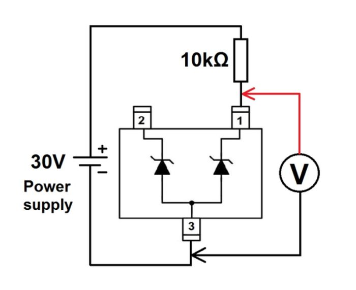
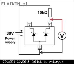
2) Testing the diode in the reverse direction:Build a simple circuit as shown in the picture below. You will need a laboratory power supply, a multimeter and a resistor. Set the laboratory power supply to the 30V (or even better 32V, if it allows it) and measure the voltage across the diode. If the diode is fine, you should read a voltage of about 27V.
Bane24 wrote:Mam pytanie czy podczas testu rezystancji na diodzie ma znaczenie (czerwona sonda na anodzie, czarna na katodzie) która sonda multimetru jest na anodzie a która na katodzie
No, it doesn't matter.
This method of testing is not reliable, as the measurement is very dependant on the diode and also on the multimeter itself. In any case, the resistance must be quite high or even beyond the range of the multimeter at both polarities of the test leads. However, if you measure a low resistance (less than 1kΩ) across the diode with a multimeter in any direction, the diode is definitely damaged.
The best way to test a diode is to perform a voltage drop test in both directions – in the forward as well as reverse orientation of the diode.