
Forum rules: Click here to view the forum rules
- Topic title should contain: the device's manufacturer, full model and the brief description of problem.
- Topic message should contain: the PCB marking code (required in case of hardware repairs), an extended description of problem, things you have checked/replaced/measured, your conclusions and the question. If you are not able to find the PCB marking code, please read THIS TOPIC. If you still cannot locate the PCB markings, please upload a clean, both-side photos of the mainboard - it is required to remove any films, modules or brackets possibly covering these markings.
- Before posting a new topic please read all topics in TRAININGS subforum and make a preliminary diagnostic based on the content of those trainings.
- Uploading of any complete schematics, BIOS / firmware files or any other kind of documentation, or linking to 3rd party websites with such files, is STRICTLY PROHIBITED. You can only upload the small portion of documentation or, link to BIOS file on UNVERIFIED BIOS FILES subforum, which simplifies the diagnostics/repair. You are not allowed to upload more then one complete page of instruction/schematic per single topic. The file you upload must not contain any watermarks, "confidential" markings, links or email addresses and cannot be password-protected.
- It is only permitted to describe one faulty device per single topic - you should always open a new topic for each subsequent device.
- Requesting of the full schematics, BoardView files, BIOS files or any other kind of documentation is NOT ALLOWED in this subforum. If you need to ask for any of these, you should open a new topic in DOCUMENTATION/BIOS REQUEST subforum.

Re: Karta graficzna MXM MS-1W0V1 zwarcie na zasilaniu
by Google Adsense [BOT] • 25 June 2025, 11:22

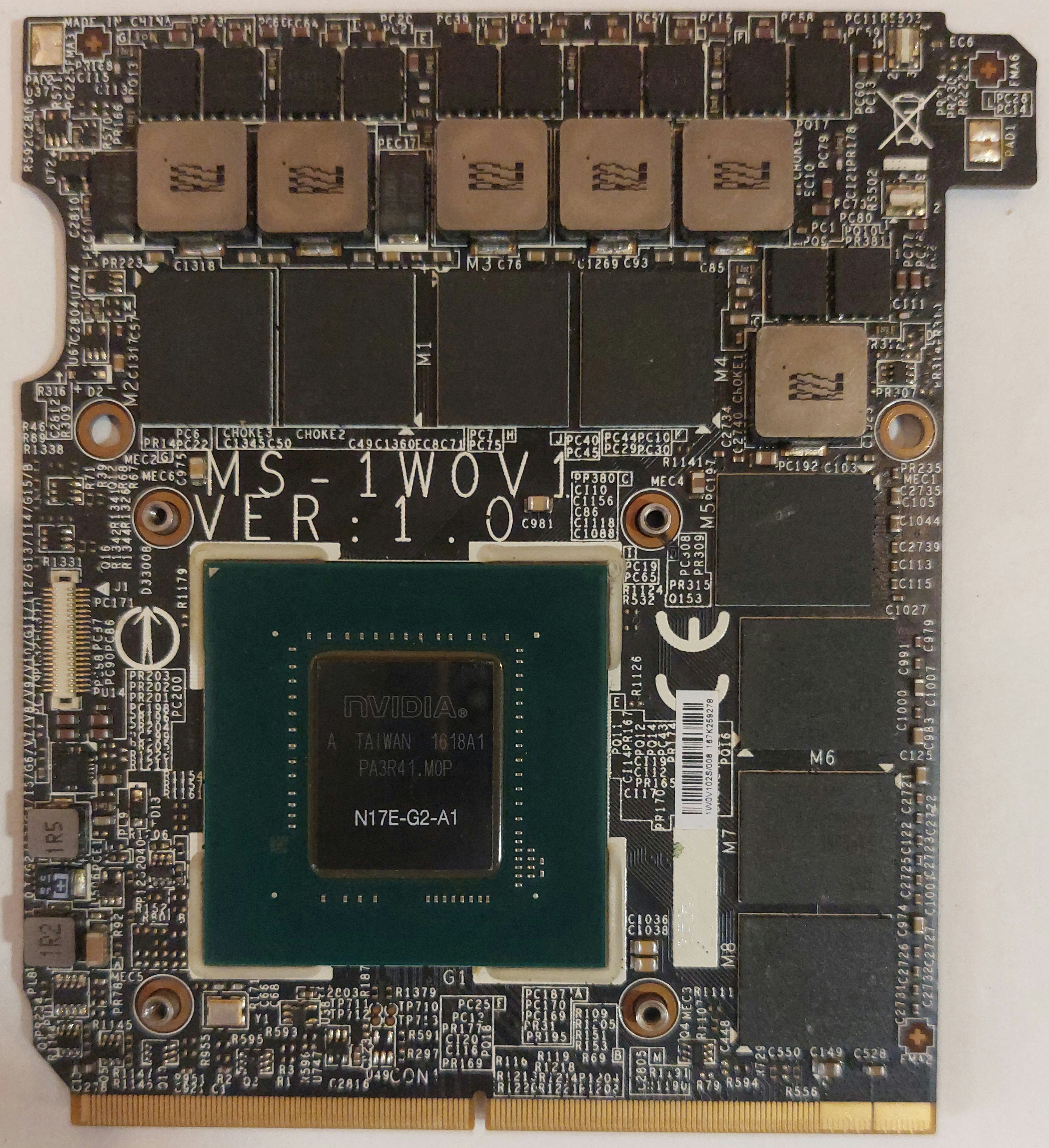
No jeśli rdzeń i pamięci są odizolowane od głównej gałęzi zasilania bo mosfety są sprawne to możesz podać wyższe napięcie bo karta na złączu MXM nie jest zasilana z 1V tylko z linii głównej (12-19V zależy w czym to pracuje) bo tak rozumiem twoją informacje "zwarcie w zasilaniu" czyli na tych dużych padach z prawej strony z pierwszego zdjęcia
Dlatego napisałem żebyś sprawdził czy mosfety nie są przebite, jak nie są to zasilanie nie pójdzie na rdzeń. Nie za bardzo wiem o co Ci chodzi z tymi "kondensatorami blokującymi". No jak nie chcesz zrobić próby zwarciowej to możesz też zdejmować losowo elementy podłączone do głównej linii zasilania aż zwarcie ustąpi ale to chyba mało efektywny sposób...


PitD wrote:Uszkodzona była sekcja czwarta zasilania GPU na uP9509p.Czyli które konkretnie MOSFETy zostały uszkodzone (PQxx)?
PitD wrote:Po wymianie przebiło ponownie.Przebiły dokładnie te same MOSFETy?
PitD wrote:Stricte "mosfetów" tutaj nie maNo jak nie ma, jak są? CSD87350 to w istocie - i jedynie - dwa asymetryczne MOSFETy, zamknięte w jednej obudowie dla zredukowania zajmowanej przez przetwornicę wielofazową powierzchni PCB. Złożona nazwa elementu w nocie katalogowej to zwyczajny chwyt reklamowy, na który chyba zbyt szybko dałeś się nabrać.
ELVIKOM LAB Ltd - Apple Repairs & PCB Design - Free Quotes! https://www.elvikom.co.uk
Jeśli skorzystałeś z mojej pomocy na Forum, możesz w ramach podziękowania wspomóc jego rozwój. Kliknij tutaj, aby dowiedzieć się więcej.
Jeśli skorzystałeś z mojej pomocy na Forum, możesz w ramach podziękowania wspomóc jego rozwój. Kliknij tutaj, aby dowiedzieć się więcej.


Remove the burned transistor PQ20 from the board and perform the following measurements:
- Measure the resistances to ground on pins 20, 21, 23 of chip uP9509P.
- Measure the resistances between listed pins of chip uP9509P:
a) Between pin 1 and pin 2.
b) Between pin 2 and pin 24.
c) Between pin 17 and pin 18.
d) Between pin 17 and pin 19.
e) Between pin 20 and pin 21.
f) Between pin 21 and pin 23.
Resistances to ground on pins of chip uP9509P
20 9kΩ
21 126kΩ
23 23kΩ
Measured the resistances between listed pins of chip uP9509P:
a) Between pin 1 and pin 2 18MΩ
b) Between pin 2 and pin 24 1.2MΩ
c) Between pin 17 and pin 18 1.2MΩ
d) Between pin 17 and pin 19 1.2MΩ
e) Between pin 20 and pin 21 240kΩ
f) Between pin 21 and pin 23 167kΩ
20 9kΩ
21 126kΩ
23 23kΩ
Measured the resistances between listed pins of chip uP9509P:
a) Between pin 1 and pin 2 18MΩ
b) Between pin 2 and pin 24 1.2MΩ
c) Between pin 17 and pin 18 1.2MΩ
d) Between pin 17 and pin 19 1.2MΩ
e) Between pin 20 and pin 21 240kΩ
f) Between pin 21 and pin 23 167kΩ
ELVIKOM LAB Ltd - Apple Repairs & PCB Design - Free Quotes! https://www.elvikom.co.uk
Jeśli skorzystałeś z mojej pomocy na Forum, możesz w ramach podziękowania wspomóc jego rozwój. Kliknij tutaj, aby dowiedzieć się więcej.
Jeśli skorzystałeś z mojej pomocy na Forum, możesz w ramach podziękowania wspomóc jego rozwój. Kliknij tutaj, aby dowiedzieć się więcej.
Re: Karta graficzna MXM MS-1W0V1 zwarcie na zasilaniu
by Google Adsense [BOT] • 9 July 2025, 16:01
Who is online
Users browsing this forum: No registered users and 1 guest
_______________________________All rights reserved. Unauthorised copying of this website's content or any of its part is strictly forbidden.
Any trademarks, brand names, products or services published on this website belong to their legal owners, are copyrighted and used for information purposes only.