
Forumsregeln: Die Forumsregeln lesen
- Der Titel des Themas sollte Folgendes enthalten: den Hersteller der Maschine, das vollständige Modell und die kurze Beschreibung des Fehlers.
- Die Themennachricht sollte enthalten: einen PCB-Markierungscode (im Falle von Hardware-Reparaturen), erweiterte Beschreibung des Fehlers, Was wurde überprüft/ersetzt/gemessen + Schlussfolgerungen und, die Frage. Wenn Sie keinen PCB-Markierungscode finden können, du solltest lesen DIESES THEMA. Wenn Sie immer noch keine PCB-Markierungscode finden können, laden Sie bitte ein sauberen Fotos von beiden Seiten des Motherboards - ist es erforderlich, alle Filme und Module zu entfernen, die möglicherweise diese Markierungen abdecken könnte.
- Bevor Sie ein neues Thema veröffentlichen, sollten Sie alle Themen im Unterforum AUSBILDUNGEN lesen und machen Sie eine vorläufige Diagnose basierend auf dem Inhalt dieser Ausbildungen.
- Das Hochladen vollständiger Anweisungen/Schaltpläne oder BIOS-Dateien / Firmware (oder das Verlinken auf andere Websites mit solchen Dateien) ist STRENG VERBOTEN. Sie können nur den kleinen Teil der Anweisung/Schaltplans oder den Link zur BIOS-Datei in UNVERIFIZIERTE BIOS-DATEIEN platzieren, der die Diagnose und Reparatur für den Themenautor vereinfacht. Sie können nicht mehr als eine vollständige Seite mit Anweisungen/Schaltplänen pro einzelnem Thema platzieren. Die Datei darf keine sichtbaren Wasserzeichen, "vertraulichen" Markierungen, E-Mail-Adressen usw. enthalten.
- Pro Thema darf nur eine fehlerhafte Maschine beschrieben werden. Für jede nächste Maschine sollten Sie ein neues Thema öffnen.
- Das Anfordern von Schaltplänen, Boardview, MB-Fotos, BIOS-Dateien oder Servicehandbüchern ist STRENG VERBOTEN. Wenn Sie irgendwelche von denen fragen wollen, sollten Sie ein neues Thema in DOKUMENTATION UND BIOS/EFI ANFRAGE Sub-Forum öffnen.


Re: B&R SPC900.TS77-05 Short circuit problem
von Google Adsense [BOT] • 8 Januar 2023, 07:56


ismailakyoltr hat geschrieben:I did apply 5th pin 1v 1a, any part does not heat up.Hello!
Repeat the short circuit test on pin 16 of this chip. Limit the voltage to 3V. Start with a current limit 0.5A. If nothing heats up, rise up the current to 1A.
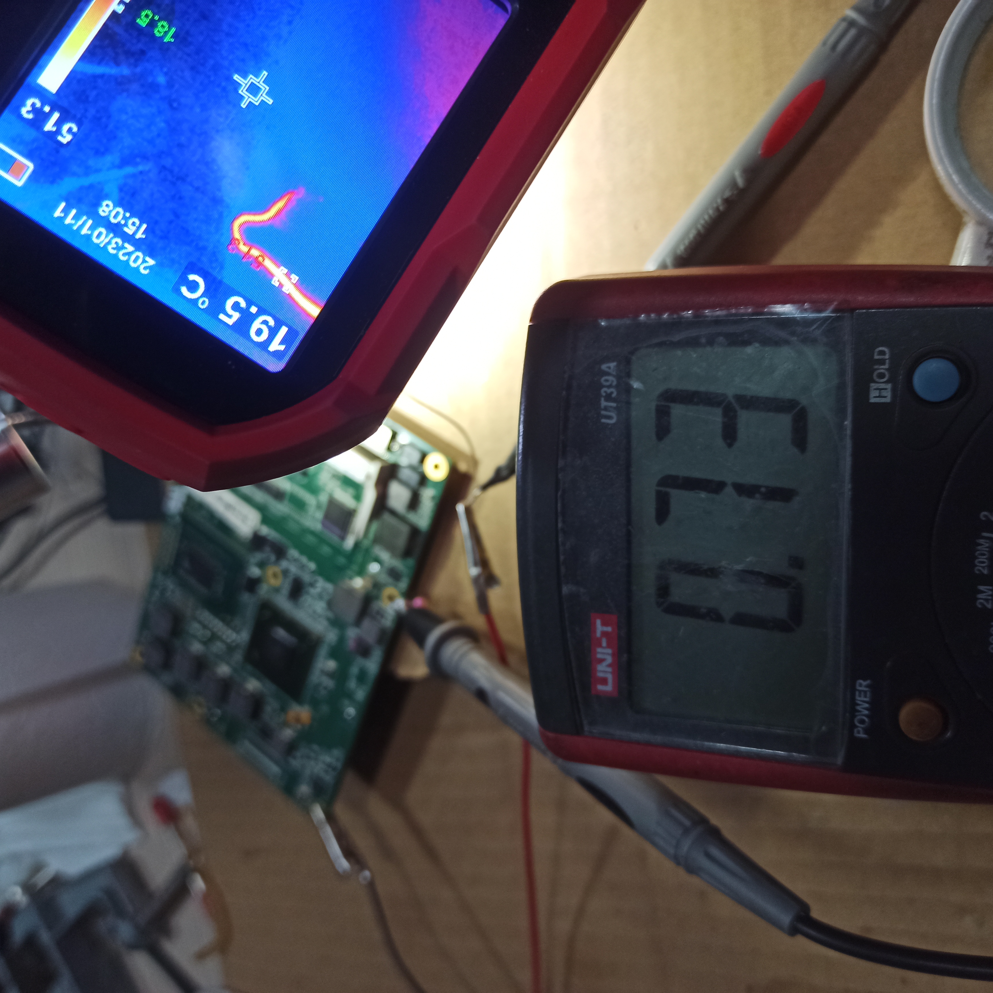
If still nothing heats up, measure the voltage on the end of test wires (at the point, where they are soldered to the board) during a short circuit test at 1A.


ELVIKOM LAB Ltd - Apple Repairs & PCB Design - Free Quotes! https://www.elvikom.co.uk
Jeśli skorzystałeś z mojej pomocy na Forum, możesz w ramach podziękowania wspomóc jego rozwój. Kliknij tutaj, aby dowiedzieć się więcej.
Jeśli skorzystałeś z mojej pomocy na Forum, możesz w ramach podziękowania wspomóc jego rozwój. Kliknij tutaj, aby dowiedzieć się więcej.
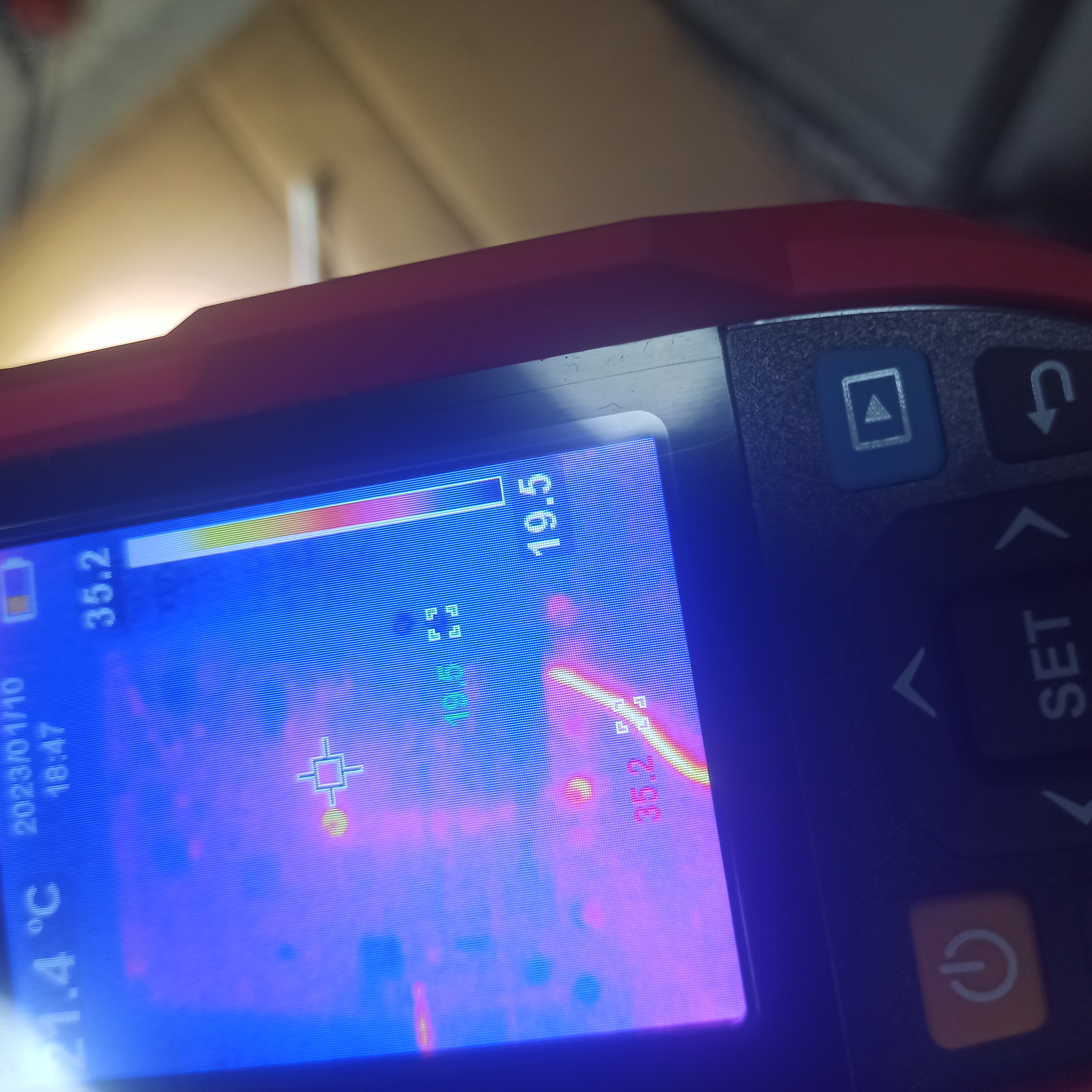
I have installed up to 1.5a but there is no heating component on the front and back.
I can't think of anything. Any chance of working with low resistance?
Even if it's bios related. I think I can't find dump bios.
I'm considering removing the CPU based on the answers from you guys.


I'm sorry I skipped this part. If it's important, I can repeat the process.
I can't think of anything. Any chance of working with low resistance?
Even if it's bios related. I think I can't find dump bios.
I'm considering removing the CPU based on the answers from you guys.
matic hat geschrieben:1A'da kısa devre testi sırasında test kablolarının ucundaki (panoya lehimlendikleri noktada) voltajı ölçün.
I'm sorry I skipped this part. If it's important, I can repeat the process.

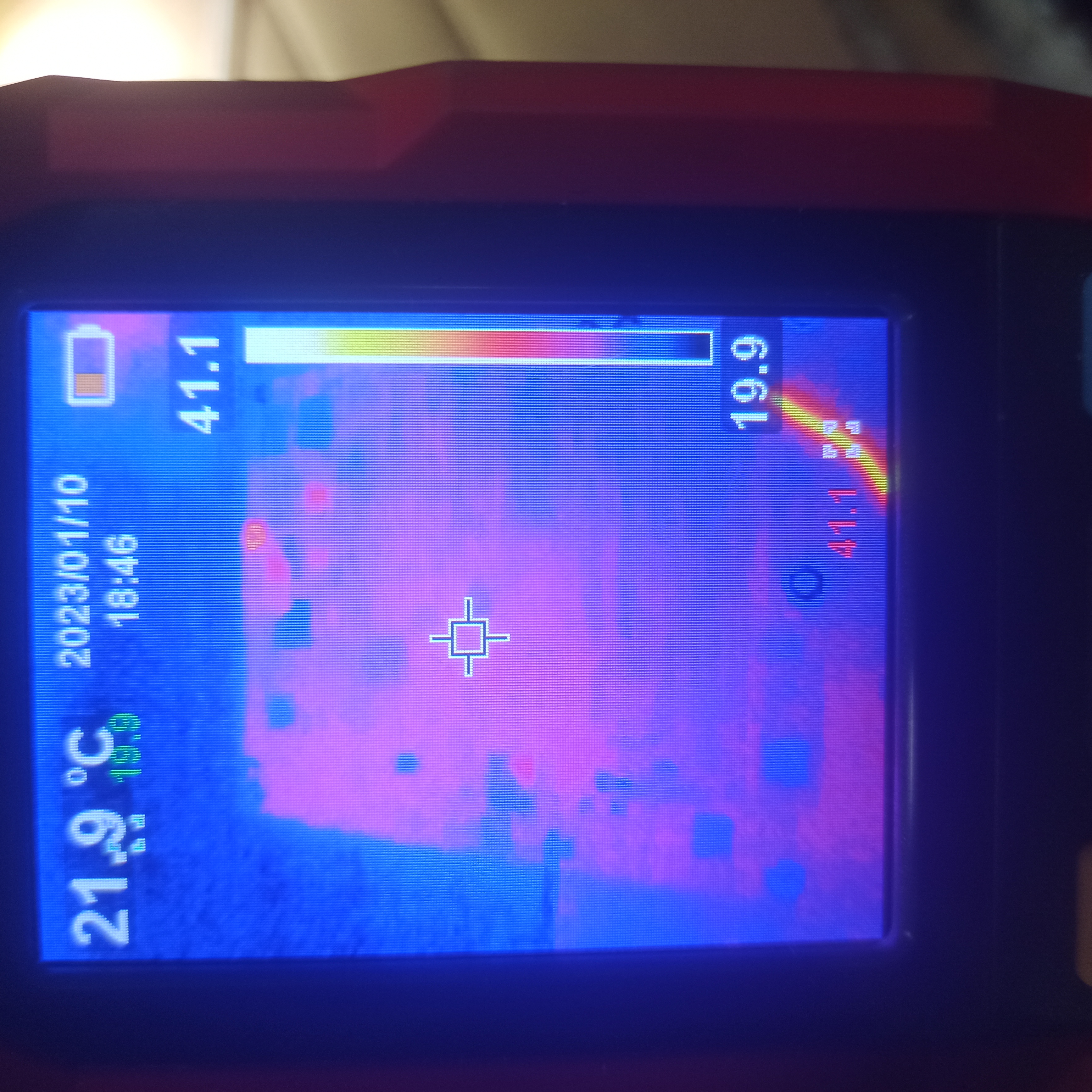
There is no short circuit at all.
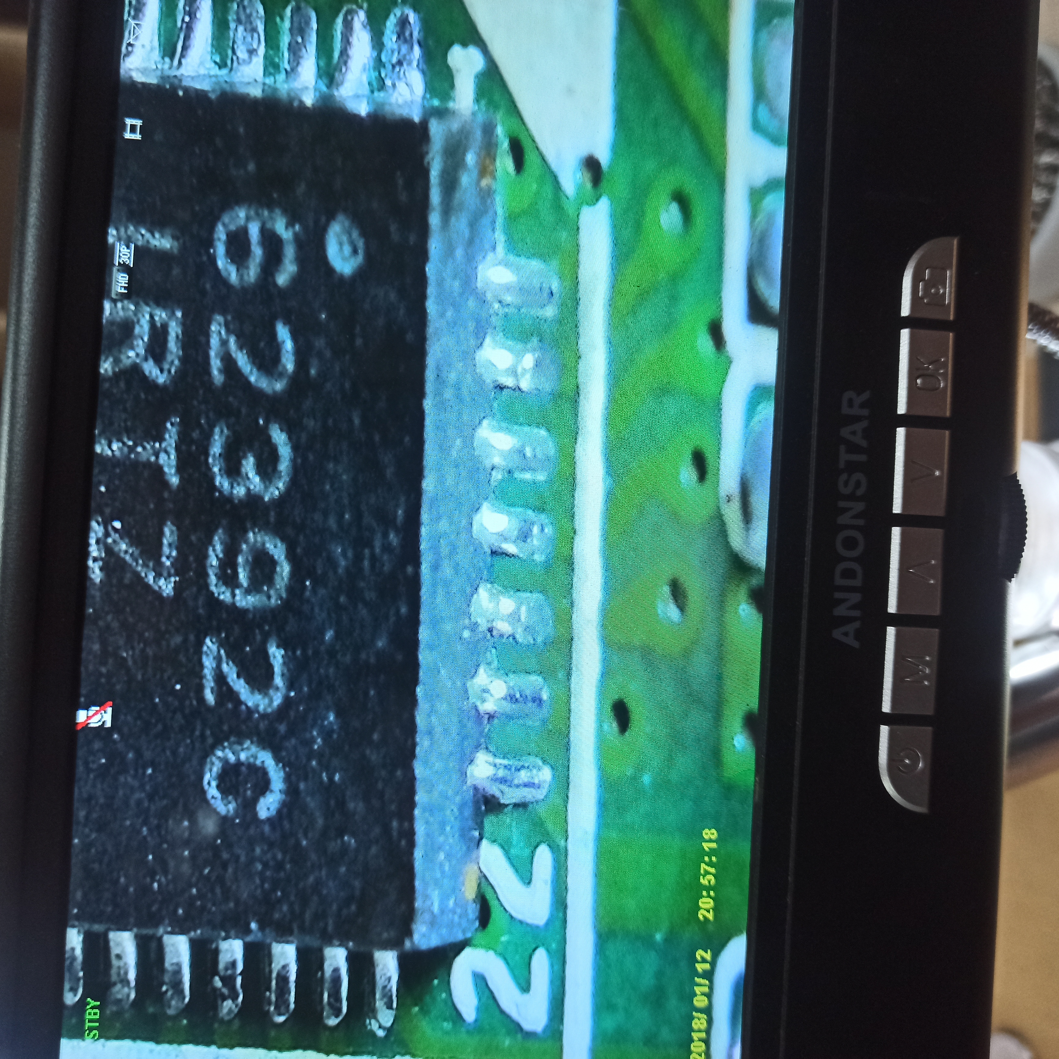
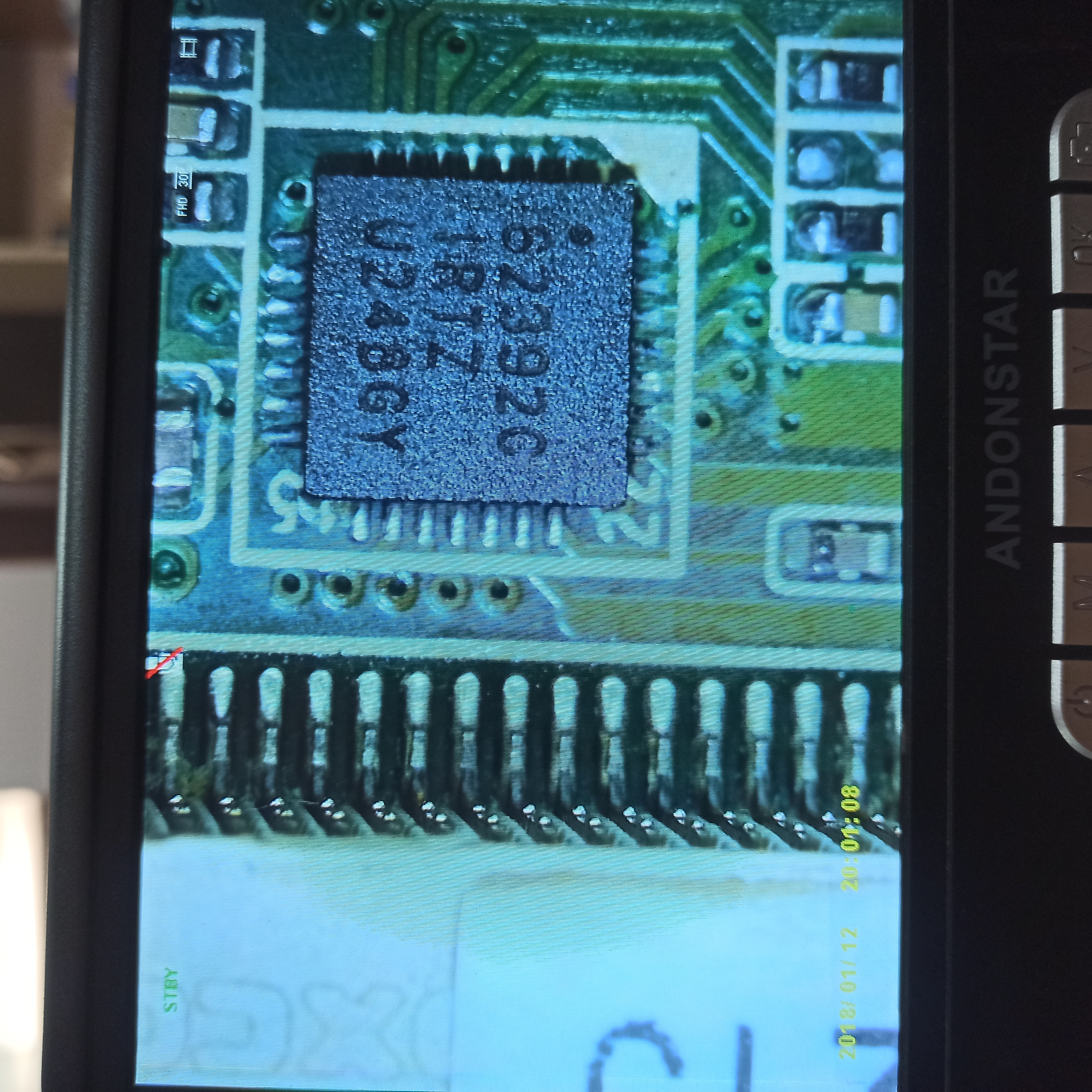
The LDO3 output of the chip ISL62392C is not used on this board. The designer of the board disabled the LDO3 regulator with connecting the enable pin to ground and this way the LDO3 output is not active and can be connected to the ground as well.
Solder the ISL chip back to its place and measure the voltages to ground on pins 1, 4, 8, 11, 14, 17, 18, 21, 24, 27 of this chip.
Re: B&R SPC900.TS77-05 Short circuit problem
von Google Adsense [BOT] • 19 Januar 2023, 07:14
Wer ist online?
Mitglieder in diesem Forum: 0 Mitglieder und 1 Gast
_______________________________Alle Rechte vorbehalten. Das unerlaubte Kopieren des Inhalts dieser Website oder eines Teils davon ist strengstens untersagt.
Alle auf dieser Website veröffentlichten Marken, Markennamen, Produkte oder Dienstleistungen gehören ihren gesetzlichen Eigentümern, sind urheberrechtlich geschützt und werden nur zu Informationszwecken verwendet.