
Hi I have a Dell Inspiron 17R 3721 (LA-9102P) It is not powering on plugged in it draws 0.01A and after press power button it drws 0.02A for around 20seconds then goes off, power LED is on whilst this happens.
19V line is ok, i have 3VALW, 5VALW, VREG3 and VREG5 are all present.
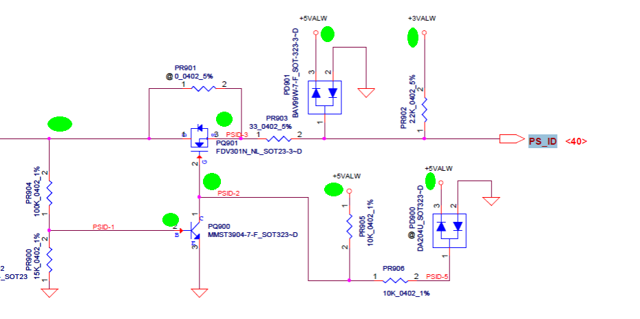
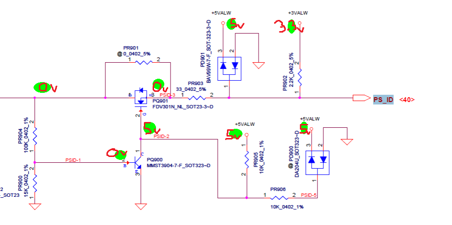
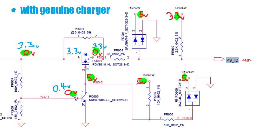
Power on/off signal drops low when button is pressed measured on KBC and KBC is getting power. I think that PCH may not be getting power? There is no PM_SLP_S signals coming from the PCH (UH1) and after inspecting the area the capacitor on top of PCH chip is reading ~0.7v after power button pressed.
If i am not mistaking PCH requires +3VS, and this is generated by QZ7 which is outputing 0.7v on pin 1,2,3 and 0V on gate pin 4. I do not know where to go from here and would appreciate your assistance. below are the measurements i have recorded. schematic is available on this site.
Thank you
PU200
-----
8 = 3.3v
17 = 5.1v
PL200 = 3.3V
PL201 = 5.1V
KBC = KB9012QF before / after pwr button
6 = PM SLP S3 - 0v / 0v
9 = 3VALW - 3.3v / 3.3v
24 = PM SLP S5 - 0v / 0v
40 = PCH_PWR_EN# - 0v / 0v
100 = EC RSMRST# - 0v / 3.3v
114 = ON/OFF - 3.3v / 0.4v (goes low)
127 = PM SLP S4 - 0v / 400mv
Capacitor on top of UH1 = 0v off plugged in / 0.7v after power button
page 35 of schematic
QZ7 +3VALW to +3VS
pin 1 - 3 = 0v / 0.7v
pin 5 - 8 = 3.3v / 3.3v
19V line is ok, i have 3VALW, 5VALW, VREG3 and VREG5 are all present.
Power on/off signal drops low when button is pressed measured on KBC and KBC is getting power. I think that PCH may not be getting power? There is no PM_SLP_S signals coming from the PCH (UH1) and after inspecting the area the capacitor on top of PCH chip is reading ~0.7v after power button pressed.
If i am not mistaking PCH requires +3VS, and this is generated by QZ7 which is outputing 0.7v on pin 1,2,3 and 0V on gate pin 4. I do not know where to go from here and would appreciate your assistance. below are the measurements i have recorded. schematic is available on this site.
Thank you
PU200
-----
8 = 3.3v
17 = 5.1v
PL200 = 3.3V
PL201 = 5.1V
KBC = KB9012QF before / after pwr button
6 = PM SLP S3 - 0v / 0v
9 = 3VALW - 3.3v / 3.3v
24 = PM SLP S5 - 0v / 0v
40 = PCH_PWR_EN# - 0v / 0v
100 = EC RSMRST# - 0v / 3.3v
114 = ON/OFF - 3.3v / 0.4v (goes low)
127 = PM SLP S4 - 0v / 400mv
Capacitor on top of UH1 = 0v off plugged in / 0.7v after power button
page 35 of schematic
QZ7 +3VALW to +3VS
pin 1 - 3 = 0v / 0.7v
pin 5 - 8 = 3.3v / 3.3v