• CNC lathe Boehringer VDF 250 C pulse encoder sensor board burned PCB

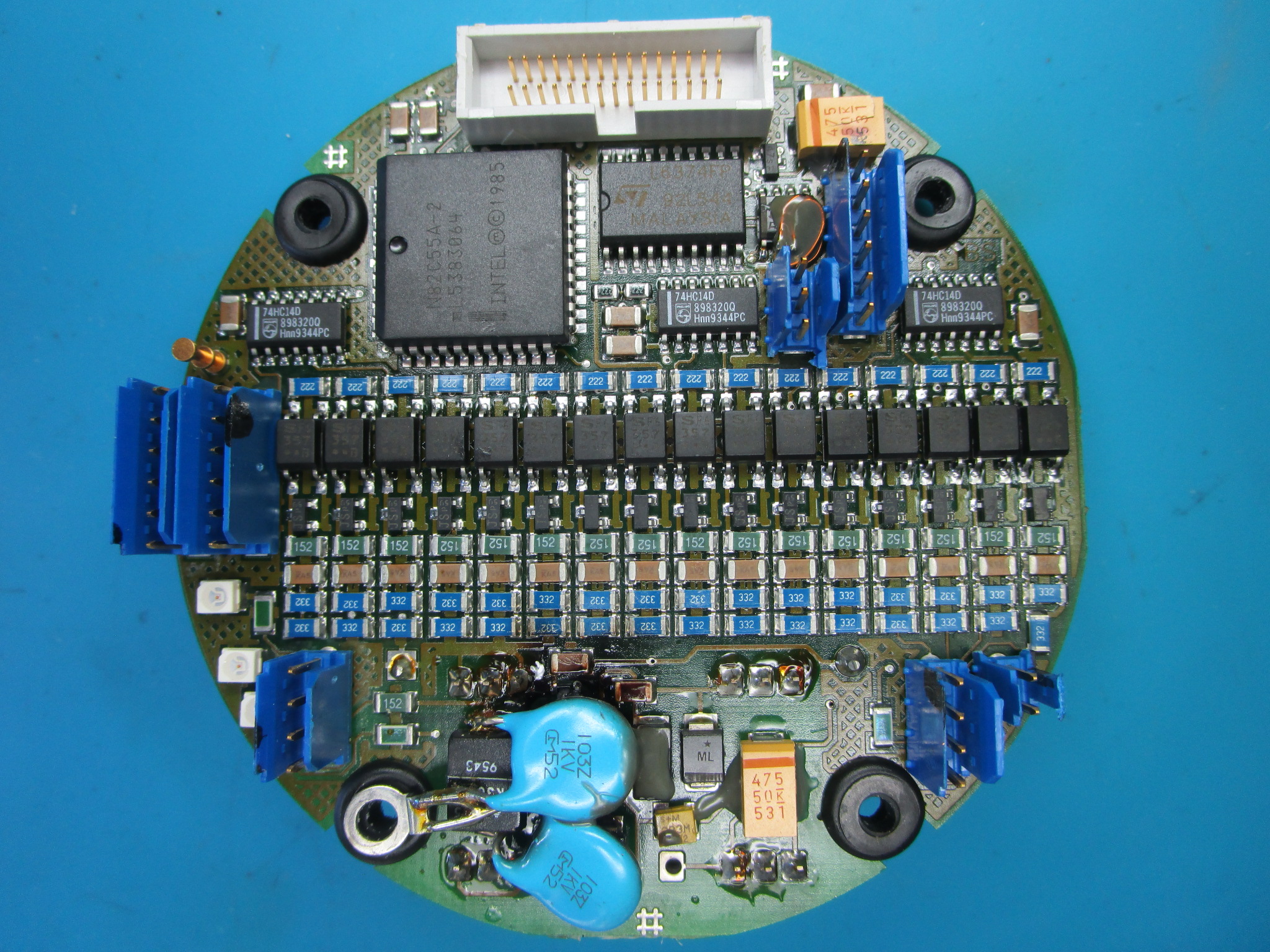
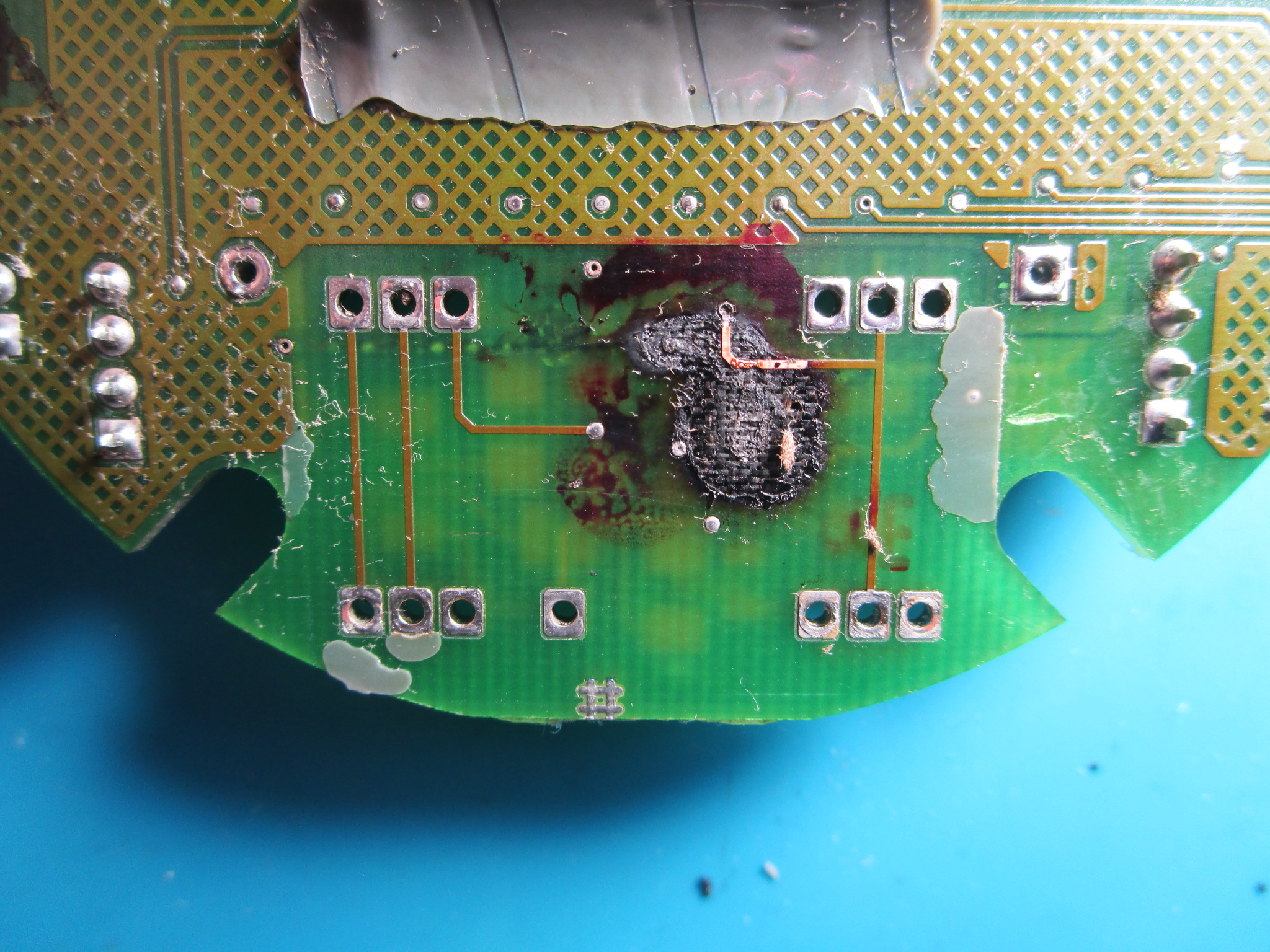
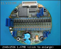
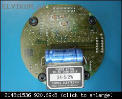
#1 CNC lathe Boehringer VDF 250 C pulse encoder sensor board burned PCB


by matic 6 October 2025, 09:46
Hello!

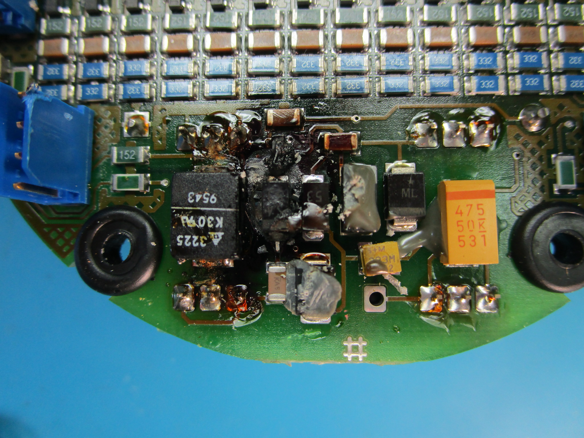
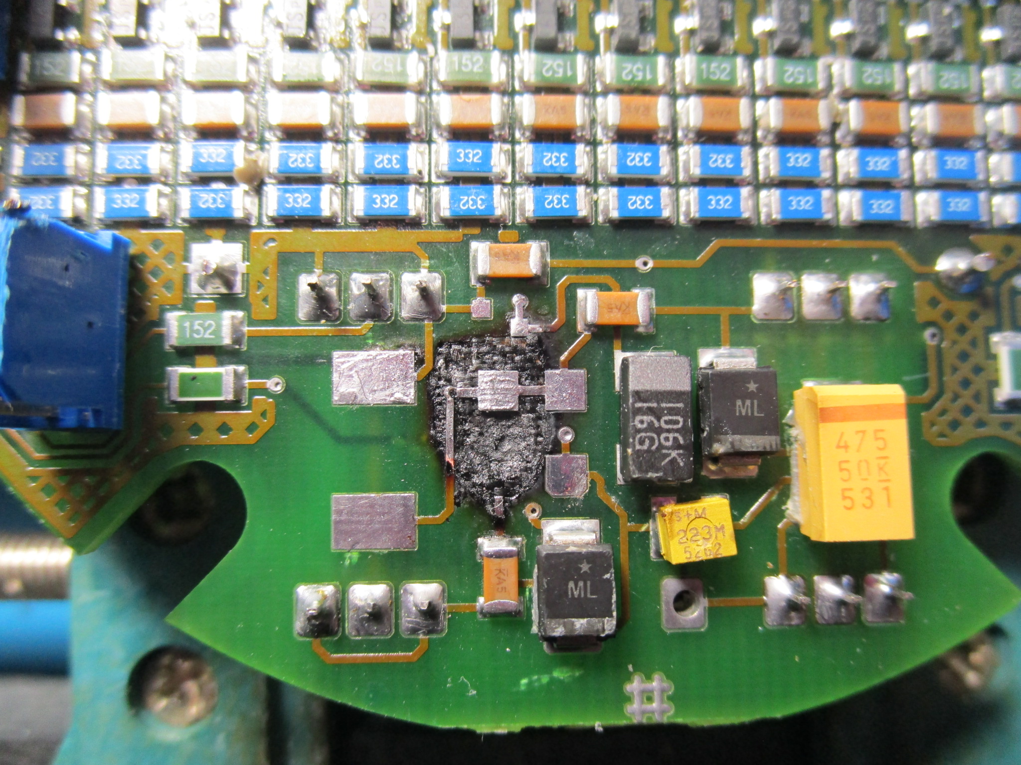
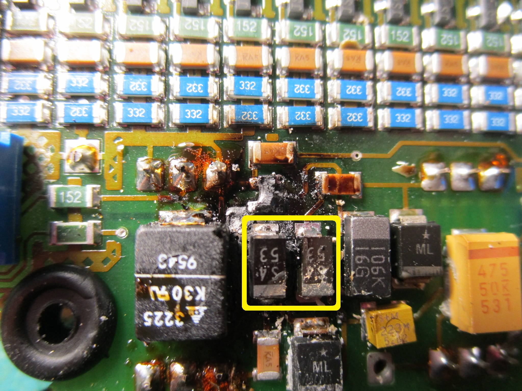
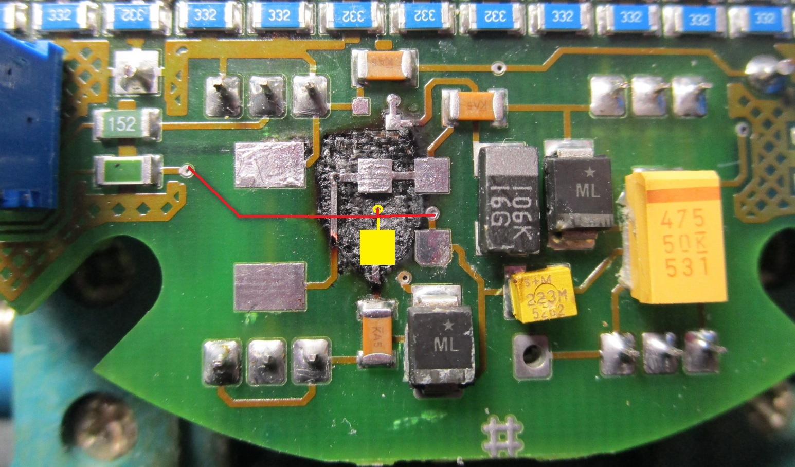
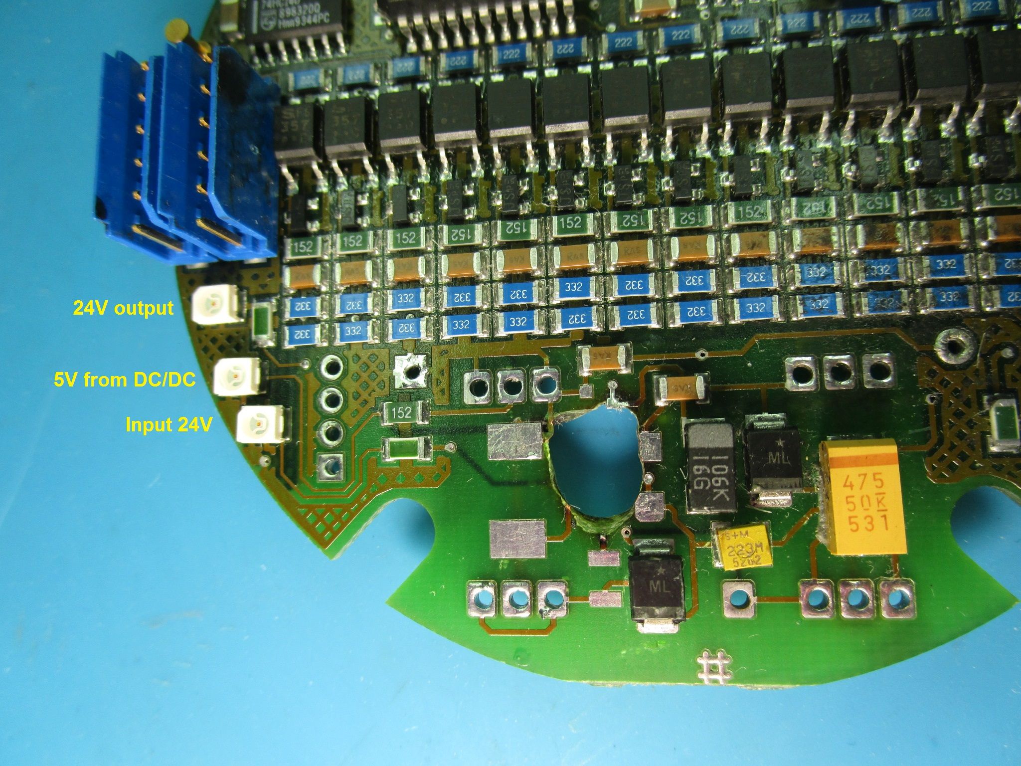
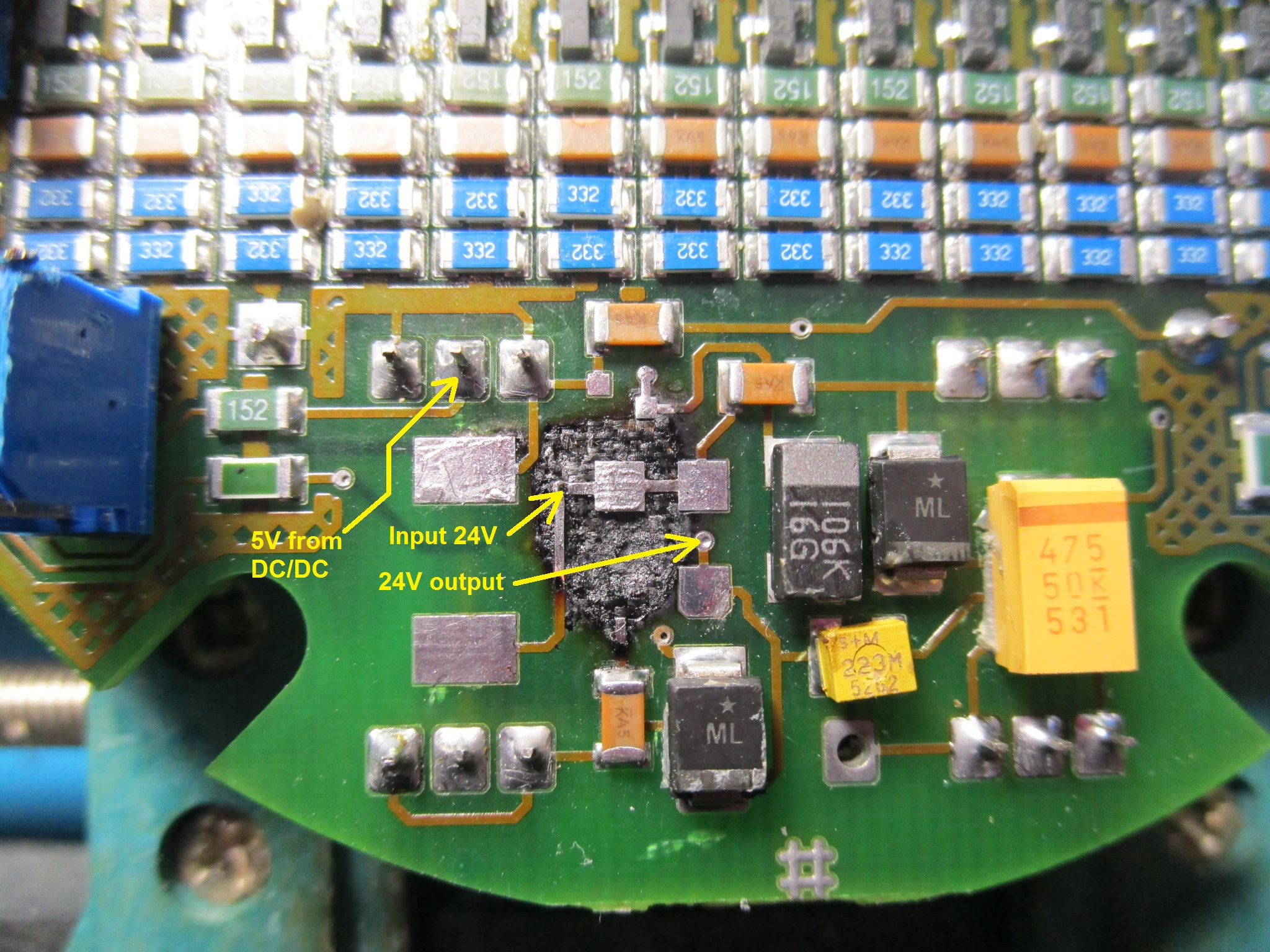
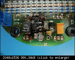
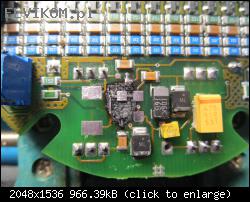
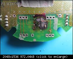
The damage was caused by a failure (short circuit) of one of the tantalum capacitors.

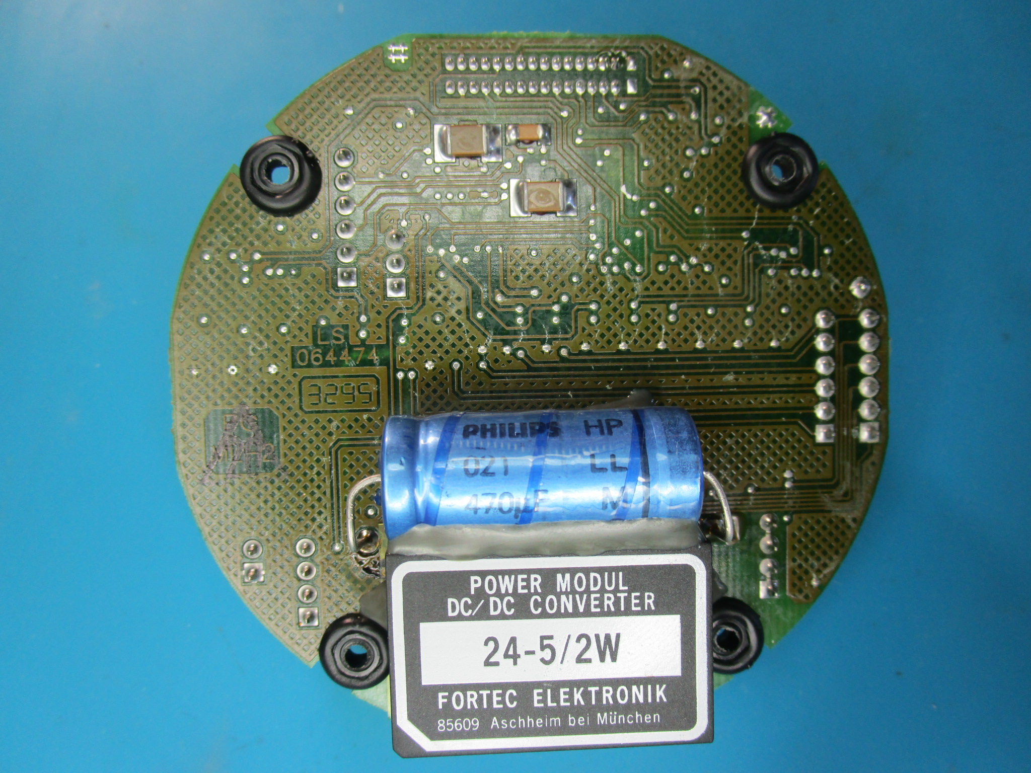
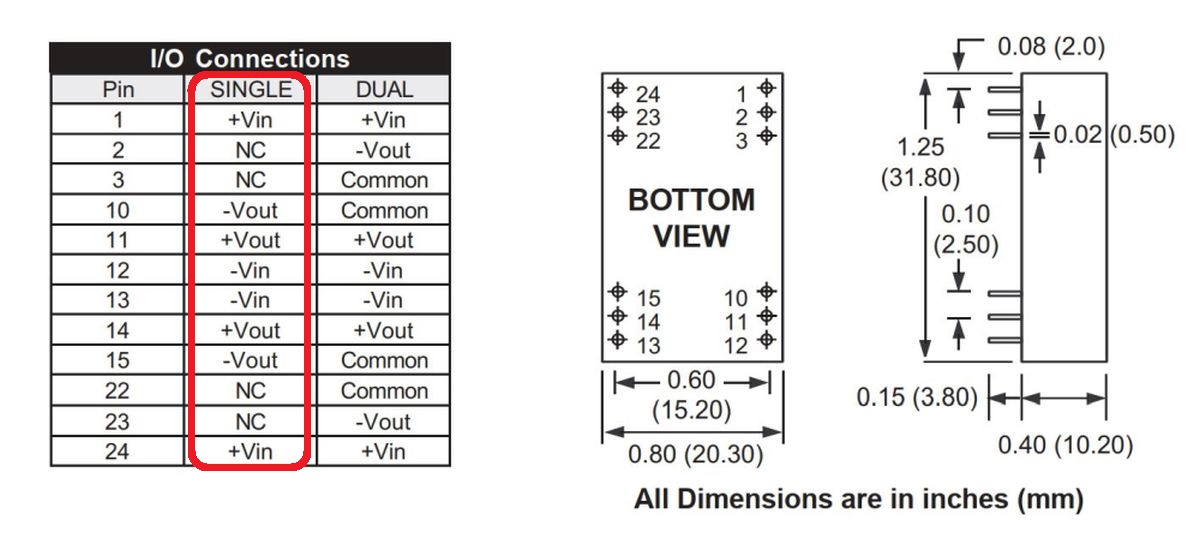
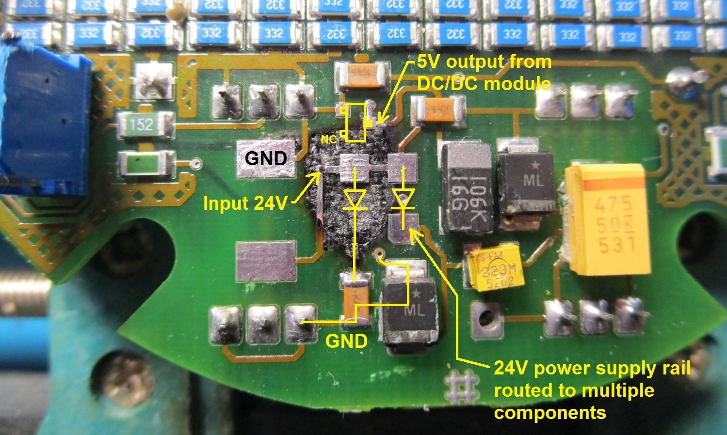
First of all I'm looking for a datasheet for the DC/DC converter module Fortec 24-5/2W in the second picture.
It's probably 24Vdc to 5Vdc/2W converter, but i'm mainly interested in the pinout. It has 12 pins, some of them are connected together.

Image Image
Image Image
Image

Re: CNC lathe Boehringer VDF 250 C pulse encoder sensor board burned PCB


by Google Adsense [BOT] 6 October 2025, 09:46

#2 Re: CNC lathe Boehringer VDF 250 C pulse encoder sensor board burned PCB


by matic 10 October 2025, 08:45
I managed to found a datasheet of some related DC/DC converter module with the same pinout:
Image
Datasheet at the attachment. The DC/DC converter module is still working.

Now I'm looking for a datasheet for the diodes marked in the picture. They are in the SMA (DO-214AC) package. One of the diodes is still working - measurements show that it's a Schottky diode.
Image


You have to be logged in to view the files attached to this post.

#3 Re: CNC lathe Boehringer VDF 250 C pulse encoder sensor board burned PCB


by matic 15 October 2025, 09:33
I managed to identify the diodes. They are SS14 (marking code S4) datasheet attached.

Damaged component in the SOT-23 package is connected between the 5V (output from the DC/DC converter module) and ground. Bottom right pin is not connected. I think is's probably an over-voltage or ESD protection device.

The last question is how to connect the damaged copper trace connected to the cathode of the left diode in the SMA package. It seems strange to me that the cathode of the left diode would be connected exclusively to the one ceramic capacitor. Perhaps both diodes in the SMA package should be connected in parallel?
Image


You have to be logged in to view the files attached to this post.

#4 Re: CNC lathe Boehringer VDF 250 C pulse encoder sensor board burned PCB


by Vogelek23 15 October 2025, 15:21
matic wrote:It seems strange to me that the cathode of the left diode would be connected exclusively to the one ceramic capacitor.
This may be some kind of inrush current limiter but not 100% sure about that. I don't think it could be a peak detector as such detector does only work with AC voltages and provides the output signal to other circuits, meaning that the cathode should be connected somewhere else in addition. There was no connection between cathodes of both diodes for sure - no single sign of track remainings on the right pad, which has a clear and sharp edge. The cathode of the left diode was probably connected elsewhere, if it was connected anywhere at all.

Because I can see no room for any additional track/connection around that missing pad, as well as no visible trace of via on the other side of PCB in this area, I would leave it as it is - with that cathode exclusively connected to a single capacitor.

EDIT: What do you think about those? It's obvious that the track marked with red line goes inside the PCB (inner layer) so it could be some via close to the missing pad (yellow line) which was connected to that track. I really see no other options here.
Image
Image

Is it possible to remove some part of that burnt PCB from the top to see if there is any sign of via underneath?

#5 Re: CNC lathe Boehringer VDF 250 C pulse encoder sensor board burned PCB


by matic 15 October 2025, 23:44
Vogelek23 wrote:What do you think about those? It's obvious that the track marked with red line goes inside the PCB (inner layer) so it could be some via close to the missing pad (yellow line) which was connected to that track.
The track marked with red goes to the "Input 24V" via connected to the anodes of both diodes (don't ask me why it's not simply connected on the top layer of the board). The other end of this track goes to the resistor which other end goes to the indication LED only. Strange enough there is another indication LED connected to the cathode of the right diode "24V output" power rail.
I also grinded the burned area of the board (layer by layer) with a Dremel and I didn't find any signs of other vias/tracks on the burned part of the board.
Image Image

I also wonder why the burned area of the board is mostly under the left diode, through which, according to the data established so far, practically no electrical current flowed, except for the short inrush current pulse that charged the ceramic capacitor (the value of this capacitor is 100nF).
I also don't see any reason why the left diode is a 1A schottky type, since a standard small rectifier diode in SOT-23 package can handle such a inrush current.

Re: CNC lathe Boehringer VDF 250 C pulse encoder sensor board burned PCB


by Google Adsense [BOT] 15 October 2025, 23:44

Who is online

Users browsing this forum: No registered users and 2 guests

_______________________________
All rights reserved. Unauthorised copying of this website's content or any of its part is strictly forbidden.
Any trademarks, brand names, products or services published on this website belong to their legal owners, are copyrighted and used for information purposes only.