


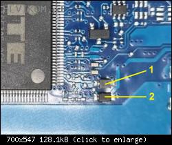
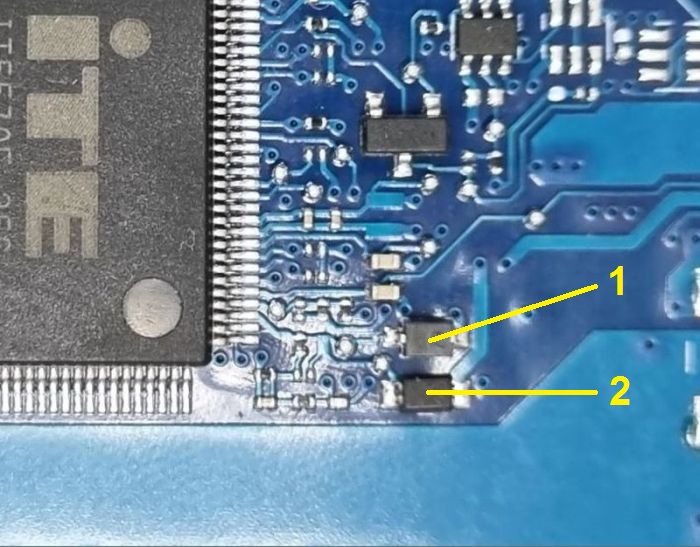
Remove the diodes 1 and 2 from the board again and keep the pin of the KBC chip lifted.
Then connect the 100kΩ resistor as shown in the following picture and connect another pin of this resistor to the laboratory power supply set to 19V. Connect the negative (-) pole of the laboratory power supply to the ground of the board. Measure the voltages to ground on points A, B, C.
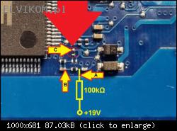
Then connect the 100kΩ resistor as shown in the following picture and connect another pin of this resistor to the laboratory power supply set to 19V. Connect the negative (-) pole of the laboratory power supply to the ground of the board. Measure the voltages to ground on points A, B, C.


