
Regole del forum: Clicca per leggere le regole del forum
- Il titolo dell'argomento deve contenere: marca e modello completo del dispositivo e la breve descrizione del problema.
- Il messaggio di argomento dovrebbe contenere: un identificatore PCB (in caso di riparazioni hardware), descrizione estesa del problema, cosa è stato controllato/sostituito/misurato, eventuali conclusioni e la domanda. Se non riesci a individuare un identificatore PCB, leggi QUESTO ARGOMENTO. Se non riesci ancora a individuare un identificatore PCB, invia foto chiare di entrambi i lati della scheda madre; è necessario rimuovere qualsiasi pellicola o altri elementi che potrebbero coprire questo identificatore.
- Prima di pubblicare un nuovo argomento, leggere tutti gli argomenti nel subforum CORSI e fare una diagnosi preliminare basata sul contenuto di questi corsi.
- È VIETATO caricare diagrami completi, file BIOS / firmware o qualsiasi altro tipo di documentazione (o collegarsi a siti Web con tali file). Puoi caricare solo una piccola parte della documentazione o collegarti al file del BIOS nel subforum BIOS FILE NON VERIFICATI. Non è consentito caricare più di una pagina completa di istruzioni/diagrami per singolo argomento. Il file che carichi non deve contenere filigrane, contrassegni "Riservati", link o indirizzi email e non può essere protetto da password.
- È consentito descrivere un solo dispositivo difettoso per singolo argomento - dovresti sempre aprire un nuovo argomento per ogni dispositivo successivo.
- La richiesta degli diagrami completi, dei file BoardView, dei file BIOS o di qualsiasi altro tipo di documentazione NON È CONSENTITA in questo subforum. Se hai bisogno di chiedere uno di questi, dovresti aprire un nuovo argomento nel subforum DOCUMENTAZIONE E RICHIESTA BIOS/EFI.

Re: PS4 FAT CUH 1216A SAC-001 problem z diodami zenera
da Google Adsense [BOT] • 28 giugno 2022, 15:09


ELVIKOM LAB Ltd - Apple Repairs & PCB Design - Free Quotes! https://www.elvikom.co.uk
Jeśli skorzystałeś z mojej pomocy na Forum, możesz w ramach podziękowania wspomóc jego rozwój. Kliknij tutaj, aby dowiedzieć się więcej.
Jeśli skorzystałeś z mojej pomocy na Forum, możesz w ramach podziękowania wspomóc jego rozwój. Kliknij tutaj, aby dowiedzieć się więcej.


Najlepiej wylutuj diodę z układu. Diody zenera nie można 100% sprawdzić miernikiem, ponieważ wykożystywany jest efekt zenera to znaczy przewodzi przy określonym napięciu. Standardowo jednak jeśli jest dobra zachowuje się jak zwykła dioda.
Można sprawdzić tak. Podłączyć diodę zaporowo w szeregu z opornikiem. Zasilić napięciem wyższym niż przewidywane napięcie zenera. Dla danego napięcia zenera i zasilania, rezystor trzeba dobrać tak aby płynął prąd Iz (z katalogu). Teraz wystarczy zmierzyć napięcie na diodzie zenera. Jeżeli przy prądzie Iz (np 5mA - dla diod 0,5W) zmierzymy mniej więcej Vz katalogowe to dioda jest dobra.
Ja do sprawdzenia szczegółowo diody zenera wykorzystuję zasilacz laboratoryjny z regulowanym napięciem i ograniczeniem prądowym. Podłączam diodę zaporowo do płynącego prądu, ogranicznik ustawiam na minimalny i powoli zwiększam napięcie. W pewnym momencie napięcie przestaje rosnąć, jest to napięcie przebicia zennera.
Dla świętego spokoju wymieniłem je ale jak wylutowałem wydaje mi się że były sprawne. A jeszcze z ciekawości to bez tych diod konsola powinna dać obraz ? Ale pojawił się problem taki że po wymianie układu i gniazda sprawdzeniu dalej konsola nie daje obrazu i przechodzi na białą diodę :/ Jesteście w stanie mi podpowiedzieć co można pomierzyć w okolicy tego układu co mogłoby się uszkodzic od wyładowania ?


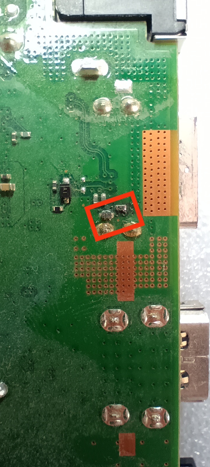
Bulo ha scritto:I teraz pytanie co to jest za układ pięcio nóżkowy zaraz za bezpiecznikiem? Stabilizator 5V? Jak mogę sprawdzić czy jest sprawny?This chip is a "Power distribution switch".
It's difficult to find the chip model, because Sony usually uses its own custom-made ICs in game consoles.
To check it, measure the voltage to ground before the fuse (on pin 4 of this chip). If there is 5V, also measure the resistance between pins 4, 5 of this chip. If the resistance is high (in kΩ range or greater), the chip is good.
matic ha scritto:Bulo ha scritto:I teraz pytanie co to jest za układ pięcio nóżkowy zaraz za bezpiecznikiem? Stabilizator 5V? Jak mogę sprawdzić czy jest sprawny?This chip is a "Power distribution switch".
It's difficult to find the chip model, because Sony usually uses its own custom-made ICs in game consoles.
To check it, measure the voltage to ground before the fuse (on pin 4 of this chip). If there is 5V, also measure the resistance between pins 4, 5 of this chip. If the resistance is high (in kΩ range or greater), the chip is good.
so far I have measured only the resistances and between these legs what you wrote is 860k ohm. I wanted to check the voltage, but I do not know exactly how to connect the cable from the power supply that I will connect 12 V to these long pins in the photo? And then I will have 5v on the output of the system, does ps4 need to be running? Earlier, when I started the console, it went straight to the white diode and now it resets once and only the second time it starts and goes into the white diode.
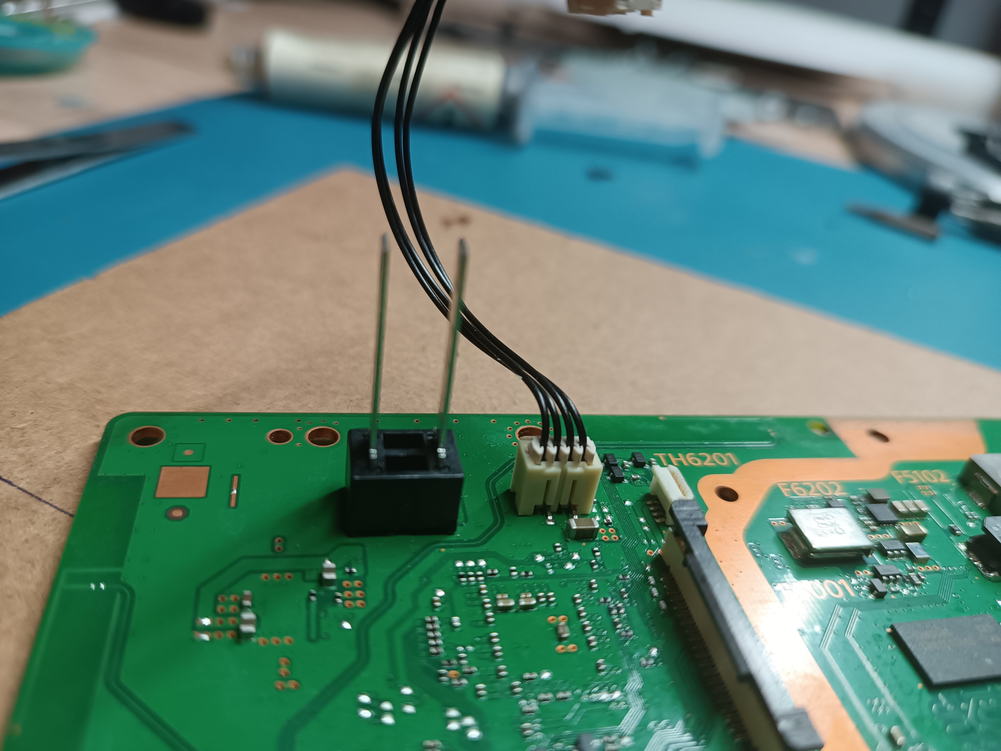
Bulo ha scritto:I wanted to check the voltage, but I do not know exactly how to connect the cable from the power supply that I will connect 12 V to these long pins in the photo?The easiest way is probably to solder a thin test wire to the pin of the fuse, where you want to measure the voltage. Then assemble the console and measure the voltage on this wire.
Bulo ha scritto:does ps4 need to be running?Yes, of course. The white LED on the console should be turned on.
matic ha scritto:Is the RTC battery good (the voltage on it must be 3V measured on the board)?
If so, try to reset the CMOS. To do this, remove the RTC battery, bridge the battery socket pins for about 20 seconds, and reconnect the RTC battery.
The battery is functional, but the reset did not do anything. The console turned on, it went to the white LED after 2 seconds, I waited a little and after 30 seconds it reset and for 15 seconds there was a blue flashing LED and after that time it turned to white and it did not reset. I have no idea anymore, maybe the storm damaged the APU? Or replace the Panasonic chip again?
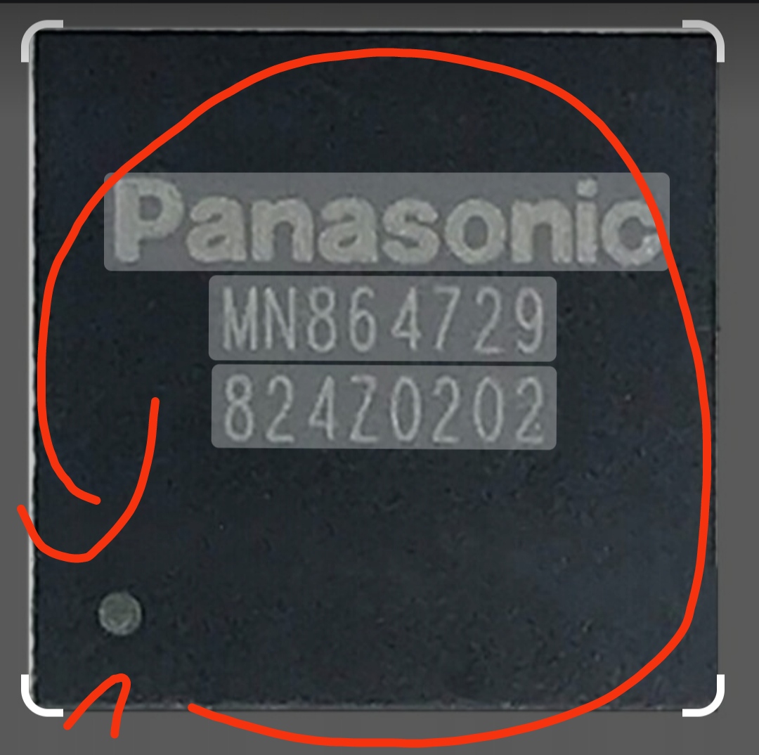
matic ha scritto:Set your multimeter to the diode test mode and measure the voltage drops to ground on pins 3, 4, 7, 8, 10, 11, 15, 16, 18, 19, 25, 28, 29, 31, 75, 76, 79, 80, 81, 82, 85, 86, 87, 88 of Panasonic chip.
These are the measurements if I was holding the red multimeter probe to ground:
Pins: (3,4)-0.4v, (7,8,10,11,15,16,18,19)-0,786v, (25,28,29)-0.462v, (31)-0.4v, (75)-0,456v, (76)-0,409v, (79,80,81,82,85,86,87)-0,456v, (88)-0,480v
When measuring, I noticed that pins 3 and 4 are shorted together, should it be?
by applying the black multimeter probe to the ground, there were other voltage drops, I also have them saved, but I think I made the first measurement by applying the red probe to the ground and the black probe to the Panasonic system legs.
I hope that I was counting the results in the right direction, to be sure I will put a photo on which I marked the direction of counting.
matic ha scritto:Bulo ha scritto:When measuring, I noticed that pins 3 and 4 are shorted together, should it be?No, they shouldn't. Check, if you have a solder bridge between this two pins. If not, remove the Panasonic chip from the board and check if the short is resolved.
I desoldered the system and there was no short circuit. After re-soldering the same circuit, all connections are the same, just between leg 3 and 4 is something wrong. On the buzzer in the multimeter it shows 103 ohms between the legs 3 and 4, but on the test of the diode between these legs there is a squeaking noise and it shows 0.088V.
Re: PS4 FAT CUH 1216A SAC-001 problem z diodami zenera
da Google Adsense [BOT] • 19 luglio 2022, 11:20
Chi c’è in linea
Visitano il forum: Nessuno e 4 ospiti
_______________________________Tutti i diritti riservati. È severamente vietata la copia non autorizzata del contenuto di questo sito Web o di qualsiasi sua parte.
Eventuali marchi, nomi di società, prodotti o servizi pubblicati su questo sito Web appartengono ai legittimi proprietari, sono protetti da copyright e utilizzati solo a scopo informativo.