
Regole del forum: Clicca per leggere le regole del forum
- Il titolo dell'argomento deve contenere: marca e modello completo del dispositivo e la breve descrizione del problema.
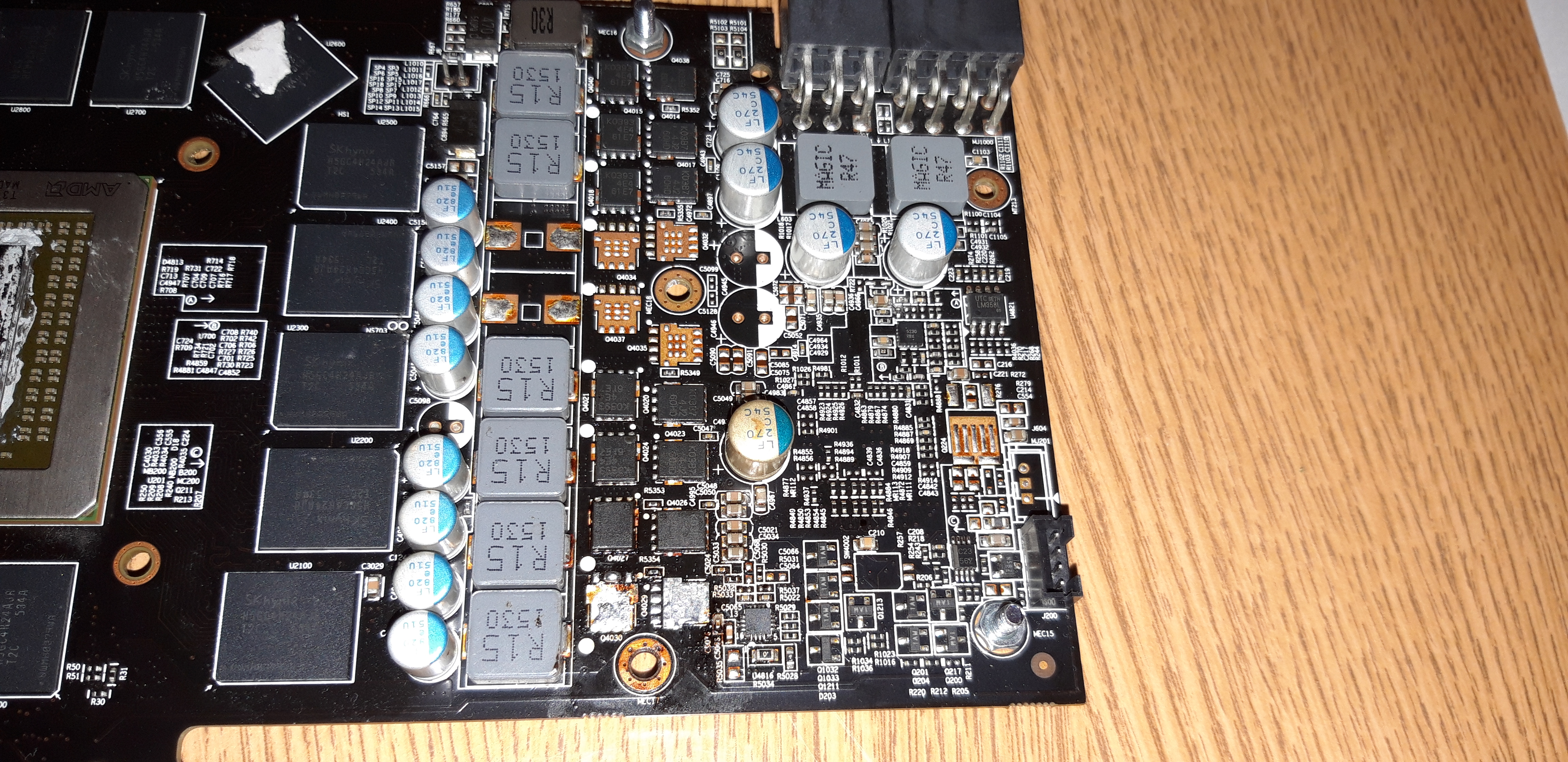
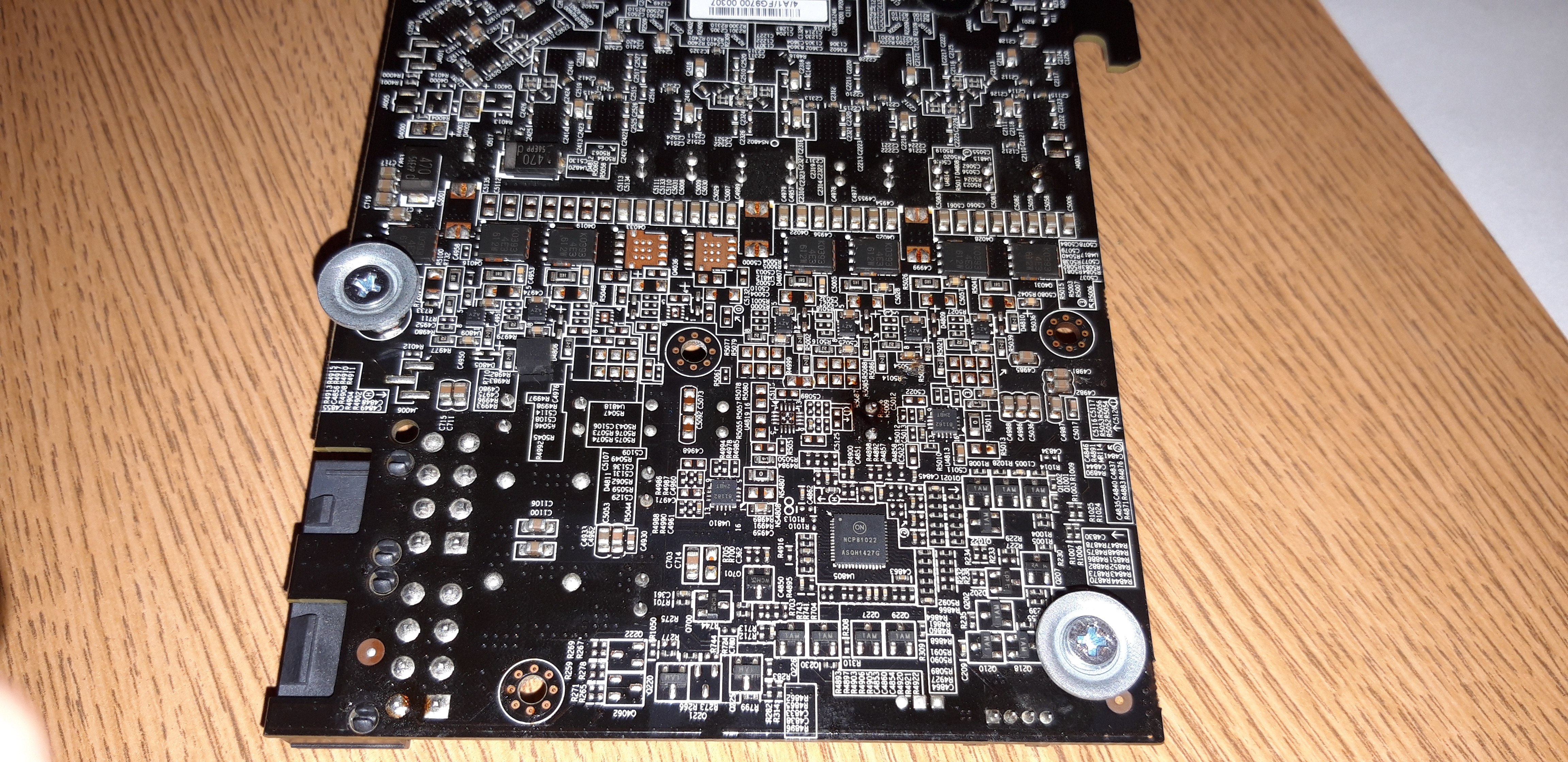
- Il messaggio di argomento dovrebbe contenere: un identificatore PCB (in caso di riparazioni hardware), descrizione estesa del problema, cosa è stato controllato/sostituito/misurato, eventuali conclusioni e la domanda. Se non riesci a individuare un identificatore PCB, leggi QUESTO ARGOMENTO. Se non riesci ancora a individuare un identificatore PCB, invia foto chiare di entrambi i lati della scheda madre; è necessario rimuovere qualsiasi pellicola o altri elementi che potrebbero coprire questo identificatore.
- Prima di pubblicare un nuovo argomento, leggere tutti gli argomenti nel subforum CORSI e fare una diagnosi preliminare basata sul contenuto di questi corsi.
- È VIETATO caricare diagrami completi, file BIOS / firmware o qualsiasi altro tipo di documentazione (o collegarsi a siti Web con tali file). Puoi caricare solo una piccola parte della documentazione o collegarti al file del BIOS nel subforum BIOS FILE NON VERIFICATI. Non è consentito caricare più di una pagina completa di istruzioni/diagrami per singolo argomento. Il file che carichi non deve contenere filigrane, contrassegni "Riservati", link o indirizzi email e non può essere protetto da password.
- È consentito descrivere un solo dispositivo difettoso per singolo argomento - dovresti sempre aprire un nuovo argomento per ogni dispositivo successivo.
- La richiesta degli diagrami completi, dei file BoardView, dei file BIOS o di qualsiasi altro tipo di documentazione NON È CONSENTITA in questo subforum. Se hai bisogno di chiedere uno di questi, dovresti aprire un nuovo argomento nel subforum DOCUMENTAZIONE E RICHIESTA BIOS/EFI.
Questo argomento è contrassegnato come D'ARCHIVIO. Rispondi solo se il tuo messaggio contiene la soluzione (Termini e Condizioni p. 12.1).

Re: Gigabyte GV-R939G1 gaming-8gd rev. 1.0 brak obrazu.
da Google Adsense [BOT] • 13 febbraio 2021, 15:54


̶̶̶̶̶̶̶̶T̶̶̶̶̶̶̶̶h̶̶̶̶̶̶̶̶e̶̶̶̶̶̶̶̶ ̶̶̶̶̶̶̶̶"̶̶̶̶̶̶̶̶D̶̶̶̶̶̶̶̶o̶̶̶̶̶̶̶̶u̶̶̶̶̶̶̶̶b̶̶̶̶̶̶̶̶l̶̶̶̶̶̶̶̶e̶̶̶̶̶̶̶̶r̶̶̶̶̶̶̶̶"̶̶̶̶̶̶̶̶ ̶̶̶̶̶̶̶̶c̶̶̶̶̶̶̶̶h̶̶̶̶̶̶̶̶i̶̶̶̶̶̶̶̶p̶̶̶̶̶̶̶̶ ̶̶̶̶̶̶̶̶h̶̶̶̶̶̶̶̶i̶̶̶̶̶̶̶̶g̶̶̶̶̶̶̶̶h̶̶̶̶̶̶̶̶l̶̶̶̶̶̶̶̶i̶̶̶̶̶̶̶̶g̶̶̶̶̶̶̶̶h̶̶̶̶̶̶̶̶t̶̶̶̶̶̶̶̶e̶̶̶̶̶̶̶̶d̶̶̶̶̶̶̶̶ ̶̶̶̶̶̶̶̶o̶̶̶̶̶̶̶̶n̶̶̶̶̶̶̶̶ ̶̶̶̶̶̶̶̶t̶̶̶̶̶̶̶̶h̶̶̶̶̶̶̶̶e̶̶̶̶̶̶̶̶ ̶̶̶̶̶̶̶̶f̶̶̶̶̶̶̶̶o̶̶̶̶̶̶̶̶l̶̶̶̶̶̶̶̶l̶̶̶̶̶̶̶̶o̶̶̶̶̶̶̶̶w̶̶̶̶̶̶̶̶i̶̶̶̶̶̶̶̶n̶̶̶̶̶̶̶̶g̶̶̶̶̶̶̶̶ ̶̶̶̶̶̶̶̶p̶̶̶̶̶̶̶̶i̶̶̶̶̶̶̶̶c̶̶̶̶̶̶̶̶t̶̶̶̶̶̶̶̶u̶̶̶̶̶̶̶̶r̶̶̶̶̶̶̶̶e̶̶̶̶̶̶̶̶ ̶̶̶̶̶̶̶̶i̶̶̶̶̶̶̶̶s̶̶̶̶̶̶̶̶ ̶̶̶̶̶̶̶̶p̶̶̶̶̶̶̶̶r̶̶̶̶̶̶̶̶o̶̶̶̶̶̶̶̶b̶̶̶̶̶̶̶̶a̶̶̶̶̶̶̶̶b̶̶̶̶̶̶̶̶l̶̶̶̶̶̶̶̶y̶̶̶̶̶̶̶̶ ̶̶̶̶̶̶̶̶d̶̶̶̶̶̶̶̶a̶̶̶̶̶̶̶̶m̶̶̶̶̶̶̶̶a̶̶̶̶̶̶̶̶g̶̶̶̶̶̶̶̶e̶̶̶̶̶̶̶̶d̶̶̶̶̶̶̶̶.̶̶̶̶̶̶̶̶ ̶̶̶̶̶̶̶̶R̶̶̶̶̶̶̶̶e̶̶̶̶̶̶̶̶m̶̶̶̶̶̶̶̶o̶̶̶̶̶̶̶̶v̶̶̶̶̶̶̶̶e̶̶̶̶̶̶̶̶ ̶̶̶̶̶̶̶̶t̶̶̶̶̶̶̶̶h̶̶̶̶̶̶̶̶i̶̶̶̶̶̶̶̶s̶̶̶̶̶̶̶̶ ̶̶̶̶̶̶̶̶c̶̶̶̶̶̶̶̶h̶̶̶̶̶̶̶̶i̶̶̶̶̶̶̶̶p̶̶̶̶̶̶̶̶ ̶̶̶̶̶̶̶̶f̶̶̶̶̶̶̶̶r̶̶̶̶̶̶̶̶o̶̶̶̶̶̶̶̶m̶̶̶̶̶̶̶̶ ̶̶̶̶̶̶̶̶t̶̶̶̶̶̶̶̶h̶̶̶̶̶̶̶̶e̶̶̶̶̶̶̶̶ ̶̶̶̶̶̶̶̶b̶̶̶̶̶̶̶̶o̶̶̶̶̶̶̶̶a̶̶̶̶̶̶̶̶r̶̶̶̶̶̶̶̶d̶̶̶̶̶̶̶̶ ̶̶̶̶̶̶̶̶a̶̶̶̶̶̶̶̶n̶̶̶̶̶̶̶̶d̶̶̶̶̶̶̶̶ ̶̶̶̶̶̶̶̶r̶̶̶̶̶̶̶̶e̶̶̶̶̶̶̶̶m̶̶̶̶̶̶̶̶e̶̶̶̶̶̶̶̶a̶̶̶̶̶̶̶̶s̶̶̶̶̶̶̶̶u̶̶̶̶̶̶̶̶r̶̶̶̶̶̶̶̶e̶̶̶̶̶̶̶̶ ̶̶̶̶̶̶̶̶t̶̶̶̶̶̶̶̶h̶̶̶̶̶̶̶̶e̶̶̶̶̶̶̶̶̶̶̶̶̶̶̶̶ ̶̶̶̶̶̶̶̶r̶̶̶̶̶̶̶̶e̶̶̶̶̶̶̶̶s̶̶̶̶̶̶̶̶i̶̶̶̶̶̶̶̶s̶̶̶̶̶̶̶̶t̶̶̶̶̶̶̶̶a̶̶̶̶̶̶̶̶n̶̶̶̶̶̶̶̶c̶̶̶̶̶̶̶̶e̶̶̶̶̶̶̶̶s̶̶̶̶̶̶̶̶ ̶̶̶̶̶̶̶̶b̶̶̶̶̶̶̶̶e̶̶̶̶̶̶̶̶t̶̶̶̶̶̶̶̶w̶̶̶̶̶̶̶̶e̶̶̶̶̶̶̶̶e̶̶̶̶̶̶̶̶n̶̶̶̶̶̶̶̶ ̶̶̶̶̶̶̶̶G̶̶̶̶̶̶̶̶a̶̶̶̶̶̶̶̶t̶̶̶̶̶̶̶̶e̶̶̶̶̶̶̶̶-̶̶̶̶̶̶̶̶S̶̶̶̶̶̶̶̶o̶̶̶̶̶̶̶̶u̶̶̶̶̶̶̶̶r̶̶̶̶̶̶̶̶c̶̶̶̶̶̶̶̶e̶̶̶̶̶̶̶̶ ̶̶̶̶̶̶̶̶a̶̶̶̶̶̶̶̶n̶̶̶̶̶̶̶̶d̶̶̶̶̶̶̶̶ ̶̶̶̶̶̶̶̶G̶̶̶̶̶̶̶̶a̶̶̶̶̶̶̶̶t̶̶̶̶̶̶̶̶e̶̶̶̶̶̶̶̶-̶̶̶̶̶̶̶̶D̶̶̶̶̶̶̶̶r̶̶̶̶̶̶̶̶a̶̶̶̶̶̶̶̶i̶̶̶̶̶̶̶̶n̶̶̶̶̶̶̶̶ ̶̶̶̶̶̶̶̶o̶̶̶̶̶̶̶̶f̶̶̶̶̶̶̶̶ ̶̶̶̶̶̶̶̶b̶̶̶̶̶̶̶̶o̶̶̶̶̶̶̶̶t̶̶̶̶̶̶̶̶h̶̶̶̶̶̶̶̶ ̶̶̶̶̶̶̶̶r̶̶̶̶̶̶̶̶e̶̶̶̶̶̶̶̶m̶̶̶̶̶̶̶̶o̶̶̶̶̶̶̶̶v̶̶̶̶̶̶̶̶e̶̶̶̶̶̶̶̶d̶̶̶̶̶̶̶̶ ̶̶̶̶̶̶̶̶t̶̶̶̶̶̶̶̶r̶̶̶̶̶̶̶̶a̶̶̶̶̶̶̶̶n̶̶̶̶̶̶̶̶s̶̶̶̶̶̶̶̶i̶̶̶̶̶̶̶̶s̶̶̶̶̶̶̶̶t̶̶̶̶̶̶̶̶o̶̶̶̶̶̶̶̶r̶̶̶̶̶̶̶̶s̶̶̶̶̶̶̶̶.̶̶̶̶̶̶̶̶ ̶̶̶̶̶̶̶̶I̶̶̶̶̶̶̶̶f̶̶̶̶̶̶̶̶ ̶̶̶̶̶̶̶̶a̶̶̶̶̶̶̶̶l̶̶̶̶̶̶̶̶l̶̶̶̶̶̶̶̶ ̶̶̶̶̶̶̶̶r̶̶̶̶̶̶̶̶e̶̶̶̶̶̶̶̶s̶̶̶̶̶̶̶̶i̶̶̶̶̶̶̶̶s̶̶̶̶̶̶̶̶t̶̶̶̶̶̶̶̶a̶̶̶̶̶̶̶̶n̶̶̶̶̶̶̶̶c̶̶̶̶̶̶̶̶e̶̶̶̶̶̶̶̶s̶̶̶̶̶̶̶̶ ̶̶̶̶̶̶̶̶w̶̶̶̶̶̶̶̶i̶̶̶̶̶̶̶̶l̶̶̶̶̶̶̶̶l̶̶̶̶̶̶̶̶ ̶̶̶̶̶̶̶̶b̶̶̶̶̶̶̶̶e̶̶̶̶̶̶̶̶ ̶̶̶̶̶̶̶̶h̶̶̶̶̶̶̶̶i̶̶̶̶̶̶̶̶g̶̶̶̶̶̶̶̶h̶̶̶̶̶̶̶̶ ̶̶̶̶̶̶̶̶(̶̶̶̶̶̶̶̶i̶̶̶̶̶̶̶̶n̶̶̶̶̶̶̶̶ ̶̶̶̶̶̶̶̶k̶̶̶̶̶̶̶̶Ω̶̶̶̶̶̶̶̶ ̶̶̶̶̶̶̶̶r̶̶̶̶̶̶̶̶a̶̶̶̶̶̶̶̶n̶̶̶̶̶̶̶̶g̶̶̶̶̶̶̶̶e̶̶̶̶̶̶̶̶ ̶̶̶̶̶̶̶̶o̶̶̶̶̶̶̶̶r̶̶̶̶̶̶̶̶ ̶̶̶̶̶̶̶̶g̶̶̶̶̶̶̶̶r̶̶̶̶̶̶̶̶e̶̶̶̶̶̶̶̶a̶̶̶̶̶̶̶̶t̶̶̶̶̶̶̶̶e̶̶̶̶̶̶̶̶r̶̶̶̶̶̶̶̶)̶̶̶̶̶̶̶̶,̶̶̶̶̶̶̶̶ ̶̶̶̶̶̶̶̶t̶̶̶̶̶̶̶̶h̶̶̶̶̶̶̶̶e̶̶̶̶̶̶̶̶ ̶̶̶̶̶̶̶̶"̶̶̶̶̶̶̶̶D̶̶̶̶̶̶̶̶o̶̶̶̶̶̶̶̶u̶̶̶̶̶̶̶̶b̶̶̶̶̶̶̶̶l̶̶̶̶̶̶̶̶e̶̶̶̶̶̶̶̶r̶̶̶̶̶̶̶̶"̶̶̶̶̶̶̶̶ ̶̶̶̶̶̶̶̶̶̶̶̶̶̶̶̶c̶̶̶̶̶̶̶̶h̶̶̶̶̶̶̶̶i̶̶̶̶̶̶̶̶p̶̶̶̶̶̶̶̶ ̶̶̶̶̶̶̶̶i̶̶̶̶̶̶̶̶s̶̶̶̶̶̶̶̶̶̶̶̶̶̶̶̶ ̶̶̶̶̶̶̶̶d̶̶̶̶̶̶̶̶a̶̶̶̶̶̶̶̶m̶̶̶̶̶̶̶̶a̶̶̶̶̶̶̶̶g̶̶̶̶̶̶̶̶e̶̶̶̶̶̶̶̶d̶̶̶̶̶̶̶̶.̶̶̶̶̶̶̶̶ ̶̶̶̶̶̶̶̶T̶̶̶̶̶̶̶̶h̶̶̶̶̶̶̶̶i̶̶̶̶̶̶̶̶̶̶̶̶̶̶̶̶̶̶̶̶̶̶̶̶s̶̶̶̶̶̶̶̶ ̶̶̶̶̶̶̶̶c̶̶̶̶̶̶̶̶h̶̶̶̶̶̶̶̶i̶̶̶̶̶̶̶̶̶̶̶̶̶̶̶̶p̶̶̶̶̶̶̶̶ ̶̶̶̶̶̶̶̶i̶̶̶̶̶̶̶̶s̶̶̶̶̶̶̶̶ ̶̶̶̶̶̶̶̶p̶̶̶̶̶̶̶̶r̶̶̶̶̶̶̶̶o̶̶̶̶̶̶̶̶b̶̶̶̶̶̶̶̶a̶̶̶̶̶̶̶̶b̶̶̶̶̶̶̶̶l̶̶̶̶̶̶̶̶y̶̶̶̶̶̶̶̶ ̶̶̶̶̶̶̶̶N̶̶̶̶̶̶̶̶C̶̶̶̶̶̶̶̶P̶̶̶̶̶̶̶̶8̶̶̶̶̶̶̶̶1̶̶̶̶̶̶̶̶1̶̶̶̶̶̶̶̶6̶̶̶̶̶̶̶̶2̶̶̶̶̶̶̶̶.̶̶̶̶̶̶̶̶
̶̶̶̶̶̶̶̶A̶̶̶̶̶̶̶̶l̶̶̶̶̶̶̶̶s̶̶̶̶̶̶̶̶o̶̶̶̶̶̶̶̶ ̶̶̶̶̶̶̶̶c̶̶̶̶̶̶̶̶h̶̶̶̶̶̶̶̶e̶̶̶̶̶̶̶̶c̶̶̶̶̶̶̶̶k̶̶̶̶̶̶̶̶ ̶̶̶̶̶̶̶̶t̶̶̶̶̶̶̶̶h̶̶̶̶̶̶̶̶e ̶̶̶̶̶̶̶̶h̶̶̶̶̶̶̶̶̶̶̶̶̶̶̶̶i̶̶̶̶̶̶̶̶g̶̶̶̶̶̶̶̶h̶̶̶̶̶̶̶̶l̶̶̶̶̶̶̶̶i̶̶̶̶̶̶̶̶g̶̶̶̶̶̶̶̶h̶̶̶̶̶̶̶̶t̶̶̶̶̶̶̶̶e̶̶̶̶̶̶̶̶d̶̶̶̶̶̶̶̶ ̶̶̶̶̶̶̶̶r̶̶̶̶̶̶̶̶e̶̶̶̶̶̶̶̶̶̶̶̶̶̶̶̶s̶̶̶̶̶̶̶̶̶̶̶̶̶̶̶̶̶̶̶̶̶̶̶̶i̶̶̶̶̶̶̶̶s̶̶̶̶̶̶̶̶t̶̶̶̶̶̶̶̶o̶̶̶̶̶̶̶̶r̶̶̶̶̶̶̶̶,̶̶̶̶̶̶̶̶ ̶̶̶̶̶̶̶̶i̶̶̶̶̶̶̶̶f̶̶̶̶̶̶̶̶ ̶̶̶̶̶̶̶̶i̶̶̶̶̶̶̶̶t̶̶̶̶̶̶̶̶ ̶̶̶̶̶̶̶̶i̶̶̶̶̶̶̶̶s̶̶̶̶̶̶̶̶ ̶̶̶̶̶̶̶̶n̶̶̶̶̶̶̶̶o̶̶̶̶̶̶̶̶t̶̶̶̶̶̶̶̶ ̶̶̶̶̶̶̶̶d̶̶̶̶̶̶̶̶̶̶̶̶̶̶̶̶a̶̶̶̶̶̶̶̶m̶̶̶̶̶̶̶̶a̶̶̶̶̶̶̶̶g̶̶̶̶̶̶̶̶e̶̶̶̶̶̶̶̶d̶̶̶̶̶̶̶̶ ̶̶̶̶̶̶̶̶(̶̶̶̶̶̶̶̶i̶̶̶̶̶̶̶̶t̶̶̶̶̶̶̶̶ ̶̶̶̶̶̶̶̶s̶̶̶̶̶̶̶̶h̶̶̶̶̶̶̶̶o̶̶̶̶̶̶̶̶u̶̶̶̶̶̶̶̶l̶̶̶̶̶̶̶̶d̶̶̶̶̶̶̶̶ ̶̶̶̶̶̶̶̶b̶̶̶̶̶̶̶̶e̶̶̶̶̶̶̶̶ ̶̶̶̶̶̶̶̶̶̶̶̶̶̶̶̶4̶̶̶̶̶̶̶̶,7̶̶̶̶̶̶̶̶Ω̶̶̶̶̶̶̶̶).̶̶̶̶̶̶̶̶

EDIT:
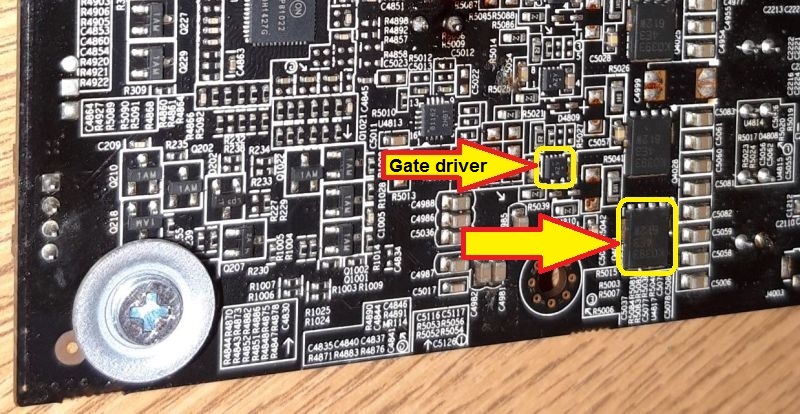
Sorry, there are dual bottom transistors on the board, so the highlighted transistor (picture below) may be guilty for a short circuit. This transistor should be replaced, regardless of whether, if it is damaged or not.
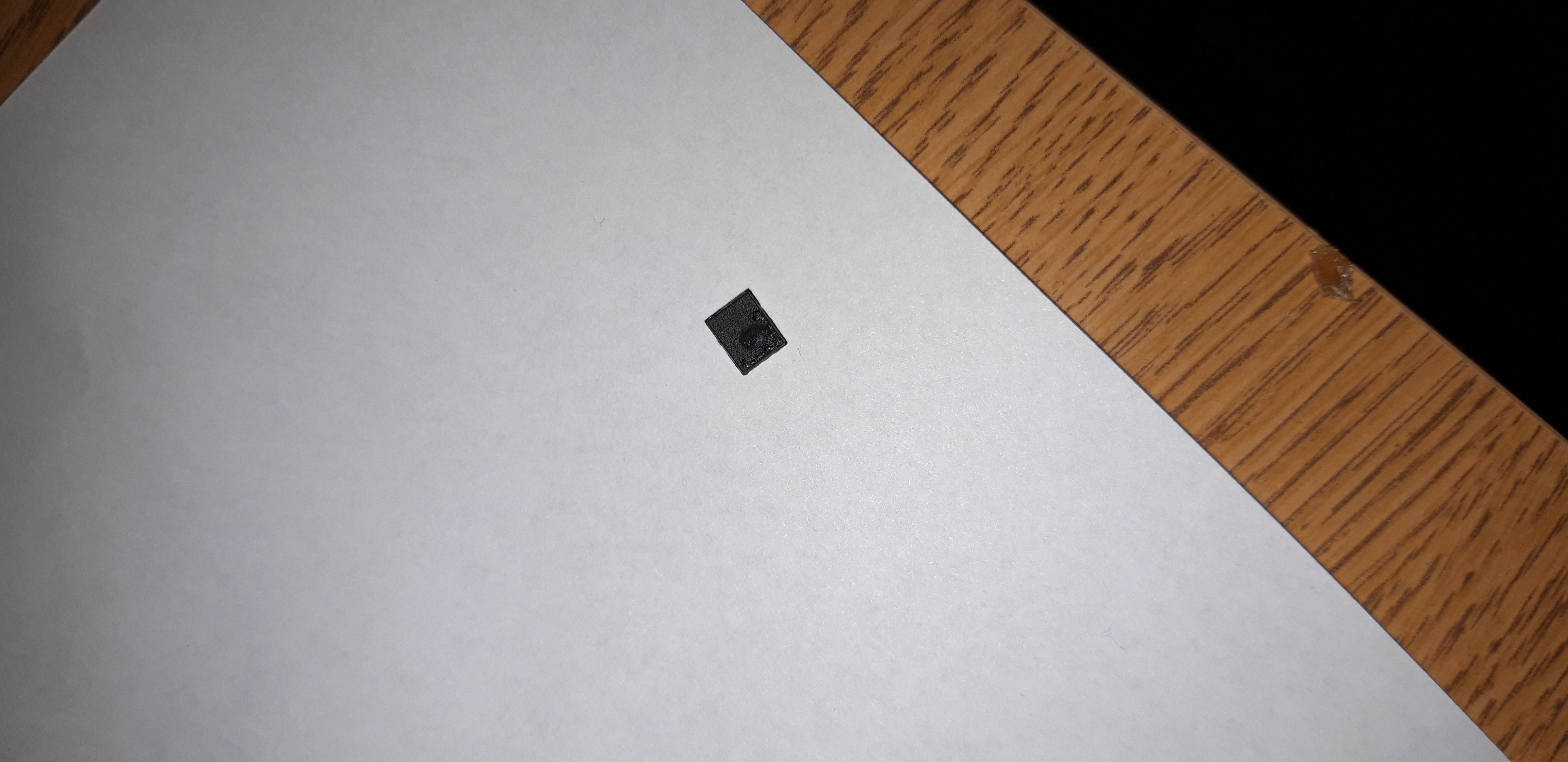
First remove this transistor from the board and check the resistances between Gate-Source and Gate-Drain of both removed transistors on the top side of the board.
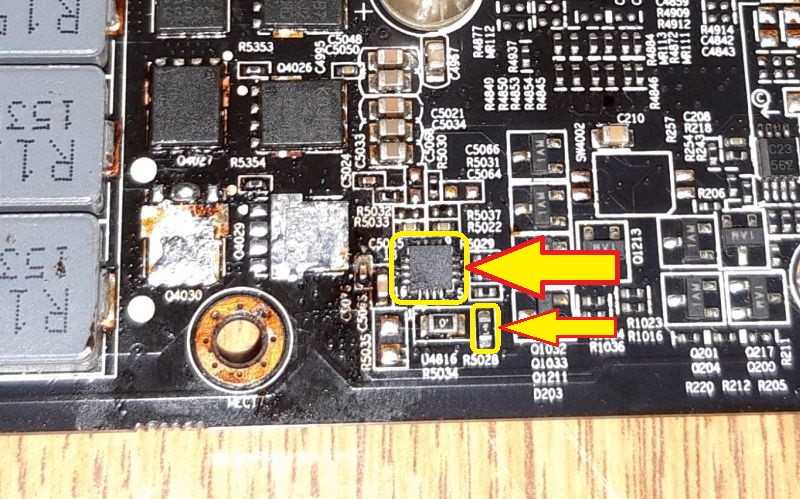
There are also separated "Gate driver" chips on the board, so if removing the suggested transistor will not resolve a short circuit, one of the the "Gate driver" chips is damaged (also highlighted on the following picture).

̶̶̶̶̶̶̶̶A̶̶̶̶̶̶̶̶l̶̶̶̶̶̶̶̶s̶̶̶̶̶̶̶̶o̶̶̶̶̶̶̶̶ ̶̶̶̶̶̶̶̶c̶̶̶̶̶̶̶̶h̶̶̶̶̶̶̶̶e̶̶̶̶̶̶̶̶c̶̶̶̶̶̶̶̶k̶̶̶̶̶̶̶̶ ̶̶̶̶̶̶̶̶t̶̶̶̶̶̶̶̶h̶̶̶̶̶̶̶̶e ̶̶̶̶̶̶̶̶h̶̶̶̶̶̶̶̶̶̶̶̶̶̶̶̶i̶̶̶̶̶̶̶̶g̶̶̶̶̶̶̶̶h̶̶̶̶̶̶̶̶l̶̶̶̶̶̶̶̶i̶̶̶̶̶̶̶̶g̶̶̶̶̶̶̶̶h̶̶̶̶̶̶̶̶t̶̶̶̶̶̶̶̶e̶̶̶̶̶̶̶̶d̶̶̶̶̶̶̶̶ ̶̶̶̶̶̶̶̶r̶̶̶̶̶̶̶̶e̶̶̶̶̶̶̶̶̶̶̶̶̶̶̶̶s̶̶̶̶̶̶̶̶̶̶̶̶̶̶̶̶̶̶̶̶̶̶̶̶i̶̶̶̶̶̶̶̶s̶̶̶̶̶̶̶̶t̶̶̶̶̶̶̶̶o̶̶̶̶̶̶̶̶r̶̶̶̶̶̶̶̶,̶̶̶̶̶̶̶̶ ̶̶̶̶̶̶̶̶i̶̶̶̶̶̶̶̶f̶̶̶̶̶̶̶̶ ̶̶̶̶̶̶̶̶i̶̶̶̶̶̶̶̶t̶̶̶̶̶̶̶̶ ̶̶̶̶̶̶̶̶i̶̶̶̶̶̶̶̶s̶̶̶̶̶̶̶̶ ̶̶̶̶̶̶̶̶n̶̶̶̶̶̶̶̶o̶̶̶̶̶̶̶̶t̶̶̶̶̶̶̶̶ ̶̶̶̶̶̶̶̶d̶̶̶̶̶̶̶̶̶̶̶̶̶̶̶̶a̶̶̶̶̶̶̶̶m̶̶̶̶̶̶̶̶a̶̶̶̶̶̶̶̶g̶̶̶̶̶̶̶̶e̶̶̶̶̶̶̶̶d̶̶̶̶̶̶̶̶ ̶̶̶̶̶̶̶̶(̶̶̶̶̶̶̶̶i̶̶̶̶̶̶̶̶t̶̶̶̶̶̶̶̶ ̶̶̶̶̶̶̶̶s̶̶̶̶̶̶̶̶h̶̶̶̶̶̶̶̶o̶̶̶̶̶̶̶̶u̶̶̶̶̶̶̶̶l̶̶̶̶̶̶̶̶d̶̶̶̶̶̶̶̶ ̶̶̶̶̶̶̶̶b̶̶̶̶̶̶̶̶e̶̶̶̶̶̶̶̶ ̶̶̶̶̶̶̶̶̶̶̶̶̶̶̶̶4̶̶̶̶̶̶̶̶,7̶̶̶̶̶̶̶̶Ω̶̶̶̶̶̶̶̶).̶̶̶̶̶̶̶̶
EDIT:
Sorry, there are dual bottom transistors on the board, so the highlighted transistor (picture below) may be guilty for a short circuit. This transistor should be replaced, regardless of whether, if it is damaged or not.
First remove this transistor from the board and check the resistances between Gate-Source and Gate-Drain of both removed transistors on the top side of the board.
There are also separated "Gate driver" chips on the board, so if removing the suggested transistor will not resolve a short circuit, one of the the "Gate driver" chips is damaged (also highlighted on the following picture).
dawido77 ha scritto:Co nazywamy odpływem bramki? Rezystancje między S - G mam zmierzoną ale teraz nie bardzo wiem jak mierzyć rezystancje między źródłem - bramką a odpływem bramki obu usuniętych tranzystorów.As far as you probably know, the MOS-FET transistor has a three pins - Gate (G), Source (S) and Drain (D).
If you know, how to measure the S - G resistance, all other resistances are similar, just mesured between the different pins of transistor.
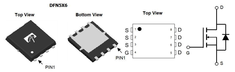
However, instead of suggested resistances, measure the resistances between listed pins of "Gate driver" chip highlighted in the second picture in post #4:
a) Between pin 1 and pin 8.
b) Between pin 4 and pin 5.
c) Between pin 5 and pin 6.
d) Between pin 7 and pin 8.
dawido77 ha scritto:Rezystancje między pinami sterownika bramki:If there is a short circuit between all of the pins, the "Gate driver" chip is damaged for sure.
1 - 8 = 0 om
4 - 5 = 0 om
5 - 6 = 0 om
7 - 8 = 0 om
Remove this chip from the board and remeasure all suggested resistances on the place of that chip. Also measure the resistance between pin 4 and pin 6 on the place of that chip.
Questo argomento è contrassegnato come D'ARCHIVIO. Rispondi solo se il tuo messaggio contiene la soluzione (Termini e Condizioni p. 12.1).
Chi c’è in linea
Visitano il forum: Nessuno e 0 ospiti
_______________________________Tutti i diritti riservati. È severamente vietata la copia non autorizzata del contenuto di questo sito Web o di qualsiasi sua parte.
Eventuali marchi, nomi di società, prodotti o servizi pubblicati su questo sito Web appartengono ai legittimi proprietari, sono protetti da copyright e utilizzati solo a scopo informativo.