• Lenovo ThinPad T470 NM-A931 rev 2.0 Schemat podłączenia JTAG MEC1653 SVOD3

Forumsregeln:Die Forumsregeln lesen

  1. Der Thementitel sollte die kurze Beschreibung des Problems enthalten
  2. Die Themenmeldung sollte die ausführliche Problembeschreibung und auch die Frage enthalten.
  3. Es ist nicht gestattet, Anhänge mit der vollständigen Dokumentation oder BIOS-Datei zu veröffentlichen oder auf Websites von Drittanbietern zu verlinken, die solche Dateien hosten. Es darf nur der kleine Teil der Dokumentation (bis zu einer Seite pro Beitrag) gepostet werden.
  4. Sie können pro Thema nur ein Problem beschreiben. Für jedes andere Problem sollten Sie ein neues Thema eröffnen.
  5. Es ist strengstens untersagt, nach Dokumentationen oder BIOS-Dateien zu fragen. Für solche Anfragen nutzen Sie bitte das DOKUMENTATION UND BIOS/EFI ANFRAGE Unterforum.
Dieses Thema ist als ARCHIV markiert. Antworten Sie nur, wenn Ihre Nachricht eine Lösung enthält (Allgemeine Geschäftsbedingungen, 12.1)

#1 Lenovo ThinPad T470 NM-A931 rev 2.0 Schemat podłączenia JTAG MEC1653 SVOD3


von AndyWilly 11 Januar 2021, 18:37
Laptop Lenovo ThinPad T470
Płyta: NM-A931 rev 2.0

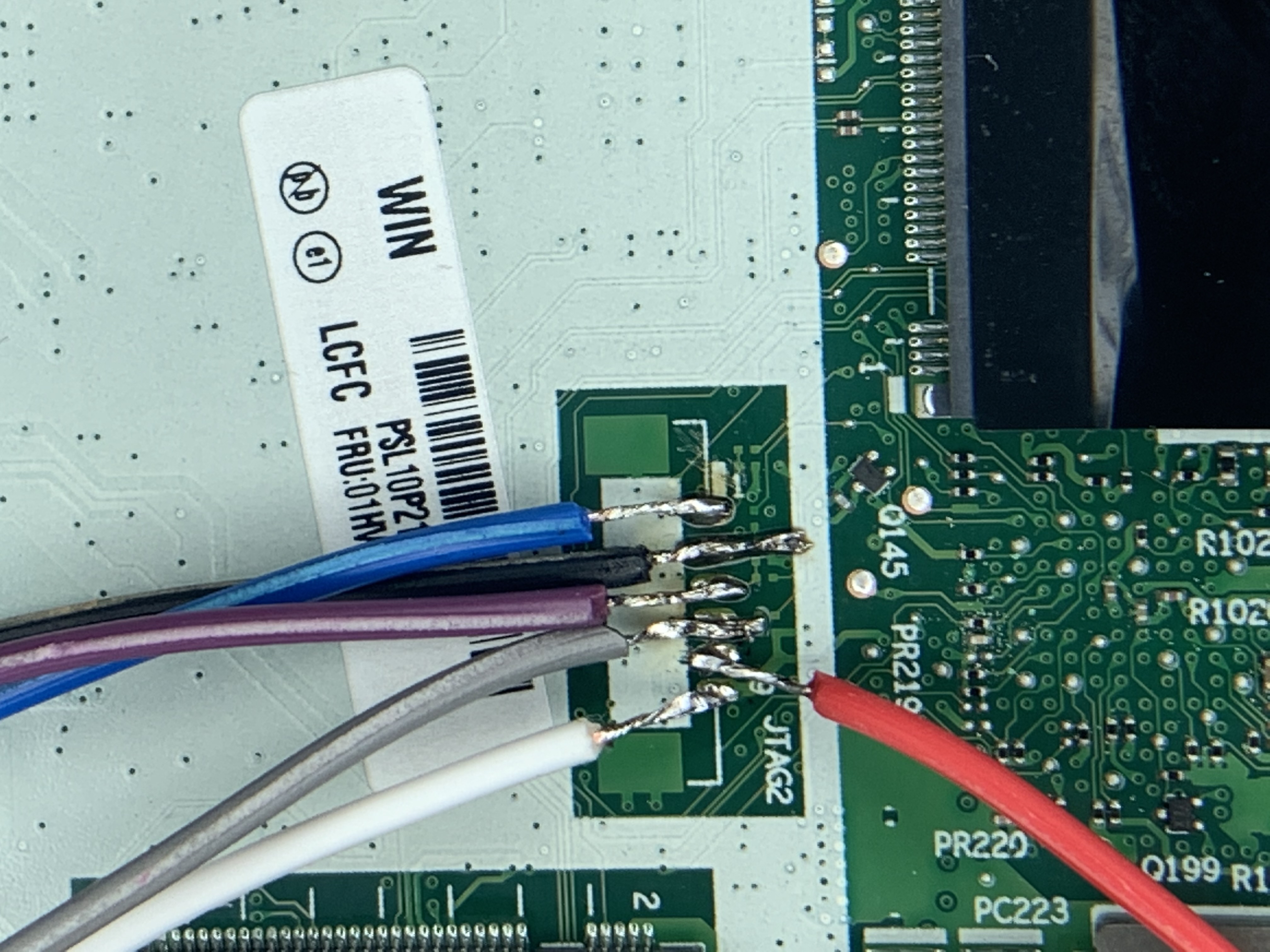
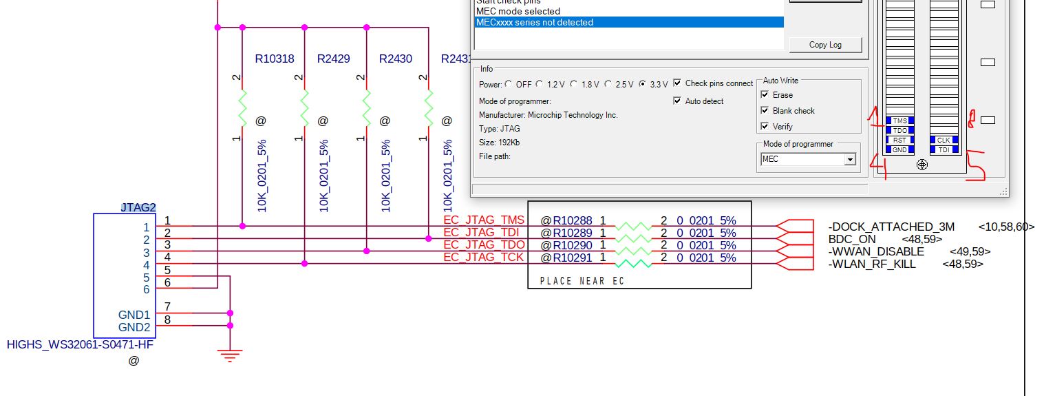
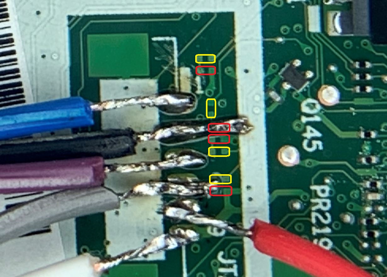
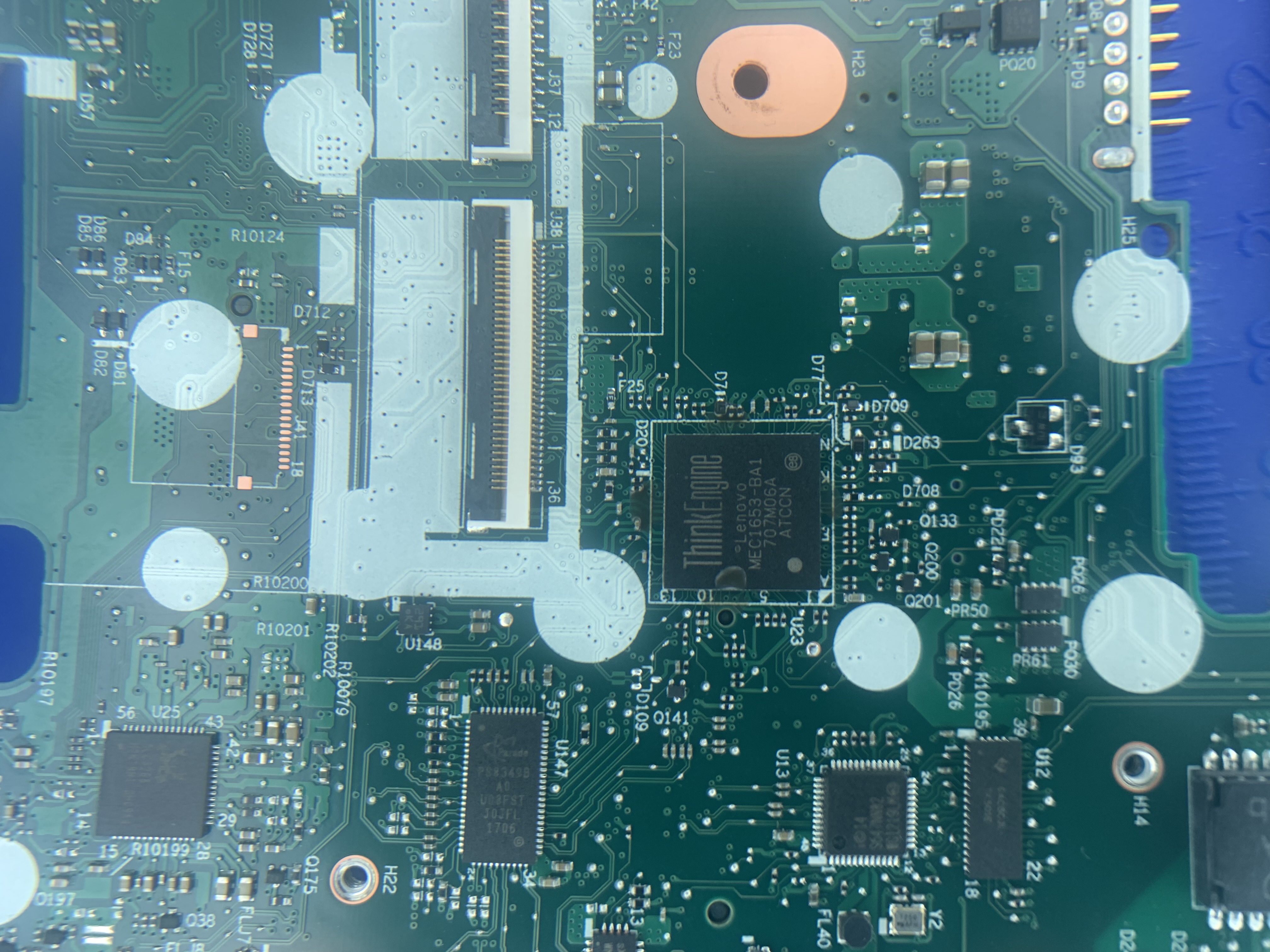
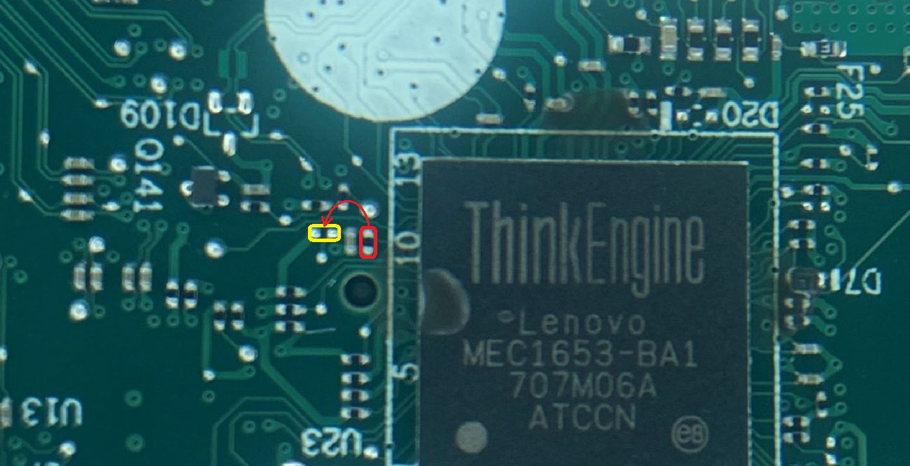
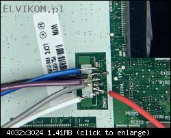
Szukam schematu podłączenia MEC1653 po interfejsie JTAG w celu jego zaprogramowania . Po podłączeniu pokazanym na zdjęciu programator SVOD3 nie wykrywa układu. Podłączam zasilanie do płyty głównej poprzez złącze zasilania nadal nie wykrywa, podawałem 3V 0,1A na pin6(JTAG) również nie wykrywa.

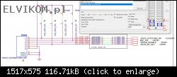
Schemat połączenia jaki użyłem:
(PIN)JTAG (PIN)SVOD3
1.TMS 1.TMS
2.TDI 5.TDI
3.TDO 2.TDO
4.TCK 6.CLK
5. GND 4.GDN
6.- .-

Bild

Bild

Re: Lenovo ThinPad T470 NM-A931 rev 2.0 Schemat podłączenia JTAG MEC1653 SVOD3


von Google Adsense [BOT] 11 Januar 2021, 18:37

#2 Re: Lenovo ThinPad T470 NM-A931 rev 2.0 Schemat podłączenia JTAG MEC1653 SVOD3


von matic 11 Januar 2021, 19:29
Hello!

First of all it is need to solder the missing components to "enable" the JTAG2 connector, because they are factory omitted to reduce the costs.
You have to solder 8 missing resistors and switch one resistor to another location.
The solder pads for missing resistors are covered with a solder mask, so you need to remove it from the pads that you will be able to solder the missing resistors. To do that it is best to use a "Fiberglass pencil" (following picture).
Bild

Solder the missing components to the highlighted locations (picture below).
Red= Resistor 10kΩ/5%, package 0201
Yellow= Resistor 0Ω (Jumper), package 0201
Bild

Plese, post a clear picture of the KBC chip area with a nearby surroundings that I can highlight the resistor, that needs to be switched to another location.

#3 Re: Lenovo ThinPad T470 NM-A931 rev 2.0 Schemat podłączenia JTAG MEC1653 SVOD3


von AndyWilly 11 Januar 2021, 20:07
Bild

#4 Re: Lenovo ThinPad T470 NM-A931 rev 2.0 Schemat podłączenia JTAG MEC1653 SVOD3


von matic 11 Januar 2021, 21:15
Switch the highlighted resistor from red to yellow position (picture below):
Bild

Re: Lenovo ThinPad T470 NM-A931 rev 2.0 Schemat podłączenia JTAG MEC1653 SVOD3


von Google Adsense [BOT] 11 Januar 2021, 21:15
Dieses Thema ist als ARCHIV markiert. Antworten Sie nur, wenn Ihre Nachricht eine Lösung enthält (Allgemeine Geschäftsbedingungen, 12.1)

Wer ist online?

Mitglieder in diesem Forum: 0 Mitglieder und 2 Gäste

_______________________________
Alle Rechte vorbehalten. Das unerlaubte Kopieren des Inhalts dieser Website oder eines Teils davon ist strengstens untersagt.
Alle auf dieser Website veröffentlichten Marken, Markennamen, Produkte oder Dienstleistungen gehören ihren gesetzlichen Eigentümern, sind urheberrechtlich geschützt und werden nur zu Informationszwecken verwendet.
cron