
Zasady działu: Kliknij, aby przejrzeć zasady tego działu
- Tytuł wątku powinien zawierać markę i pełny model sprzętu oraz skrótowy opis usterki.
- Treść wątku powinna zawierać dokładny opis usterki, co zostało sprawdzone/wymienione/zmierzone, wyniki tych działań, oznaczenie kodowe PCB (w przypadku napraw hardware) oraz sformułowane pytanie. W przypadku problemów z odczytaniem oznaczenia kodowego PCB, należy przeczytać TEN WĄTEK. Jeśli nadal nie można znaleźć oznaczenia, należy zamieścić wyraźne zdjęcia obu stron płyty - należy przy tym usunąć wszelkie folie i moduły, mogące ewentualnie zasłaniać oznaczenia płyty.
- Przed napisaniem nowego tematu, każdy użytkownik zobowiązany jest zapoznać się z wątkami w dziale SZKOLENIA i na ich podstawie dokonać próby wstępnej diagnostyki uszkodzenia.
- Nie jest dozwolone umieszczanie załączników w postaci kompletnych dokumentacji, a także jakichkolwiek wsadów BIOS / firmware (do tego służy dział PLIKI BIOS DO WERYFIKACJI). Dozwolone jest wyłącznie umieszczenie fragmentu dokumentacji, który ułatwi autorowi diagnostykę/naprawę sprzętu z wątku. W jednym poście można zamieścić nie więcej, niż jedną stronę instrukcji/schematu. Plik nie może posiadać widocznych znaków wodnych, napisów "confidential", adresów email etc.
- Nie jest dozwolone zamieszczanie linków do plików, znajdujących się na innych stronach internetowych.
- Nie jest dozwolone zakładanie tematu, który opisuje usterkę więcej niż jednego sprzętu. W takich przypadkach należy utworzyć osobne wątki dla każdego sprzętu.
- Nie jest dozwolone pisanie tematu lub postu, mającego charakter zapytania o schemat, boardview, zdjęcia płyty, wsad BIOS lub instrukcję serwisową. Do takich zapytań służy dział ZAPYTANIA O DOKUMENTACJE/BIOS.


Re: Re: Lenovo Flex 2 14" LF14M MB 13281-1 Completely Dead
przez Google Adsense [BOT] • 7 stycznia 2019, 00:58

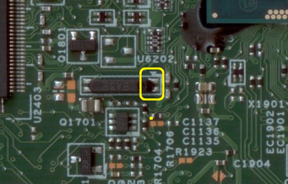
matic napisał(a):So you just want me to inject 3.3V to 3D3V_AUX_KBC_VCC or has this bridge any particular reason? Because I've got bench PSU...I think there is a broken path on the PCB, which supplies the KBC chip. Use a bridge wire, as I suggested.
Will do tomorrow, when will be back at my workshop. In the meantime, can you please explain me what would be the differene if I just supply 3.3V from bench PSU. The bridge doesn't make any sense to me. (don't mean this in a bad way, just trying to understand what's going on) Also what about circuit below? As far as I know there's no schematic for LF14M MB, so not sure if it's there or not, but every Wistron motherboards with Haswel and Nuvoton architecture has it? And I think the problem lies there.

*EDIT*
I've made the bridge, but it's till the same. No LED lights & motherboard doesn't power up and just noticed that AC_PRESENT Voltage on PIN112 of KBC fluctuates.
loser18 napisał(a):As far as I know there's no schematic for LF14M MB, so not sure if it's there or not, but every Wistron motherboards with Haswel and Nuvoton architecture has it? And I think the problem lies there.Yes, the schematic for your board is currently not available. The schematic, which I looked is without that KBC power supply switch.
Remove the jump wire and perform the following measurements:
Is the voltage on the CMOS battery correct (3V)?
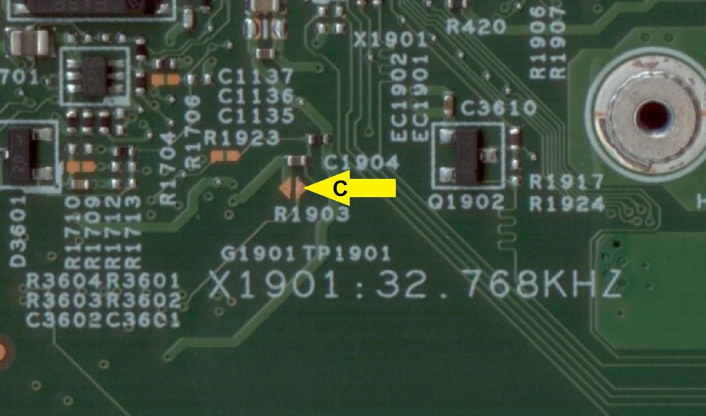
Measure the voltages to ground on both pins of RTC crystal X1901 (it is located between APU and KBC chip) without connected power supply (only CMOS battery).
Measure the voltage to ground on highlighted point "C" without connected power supply (only CMOS battery).
matic napisał(a):loser18 napisał(a):As far as I know there's no schematic for LF14M MB, so not sure if it's there or not, but every Wistron motherboards with Haswel and Nuvoton architecture has it? And I think the problem lies there.Yes, the schematic for your board is currently not available. The schematic, which I looked is without that KBC power supply switch.
Remove the jump wire and perform the following measurements:
Is the voltage on the CMOS battery correct (3V)?
Measure the voltages to ground on both pins of RTC crystal X1901 (it is located between APU and KBC chip) without connected power supply (only CMOS battery).
Measure the voltage to ground on highlighted point "C" without connected power supply (only CMOS battery).
Yep. The CMOS battery voltage is correct.
Crystal reads 0V on both sides.
Point "C" reads around 2.8V
matic napisał(a):Measure the power consumption (in mA) of the board without main battery connected.loser18 napisał(a):Crystal reads 0V on both sides.Measured on the highlighted two pins?
If so, measure it again with connected power supply.
Yes PIN 1 & 4. They actually read few mV. Same with PSU conected.
1=380mV
4=220mV
loser18 napisał(a):I've measured current with multimeter now & it draws around 0.1mAThe current consumption only 100µA seems too low. It should be around 1-10mA.
Yes PIN 1 & 4. They actually read few mV. Same with PSU conected.The quartz oscillator is connected directly to the APU hybrid.
It seems that the APU hybrid is bad.
The quartz oscillator is connected directly to the APU hybrid.
It seems that the APU hybrid is bad.
Thank you very much for your help, mate. Just want to be 100% sure before I replace the APU. What about that fluctuating AC_PRESENT signal on KBC? As far as I understand it's generated by KBC & it goes straight to APU. Couldn't be lack of the signals on crystal chip caused by this?
Re: Lenovo Flex 2 14" LF14M MB 13281-1 Completely Dead
przez Google Adsense [BOT] • 17 stycznia 2019, 01:14
Kto przegląda forum
Użytkownicy przeglądający ten dział: Brak zidentyfikowanych użytkowników i 3 gości
_______________________________Wszelkie prawa zastrzeżone. Zabrania się kopiowania jakichkolwiek treści i elementów witryny bez zezwolenia.
Wszelkie opublikowane na tej stronie znaki handlowe, nazwy marek, produktów czy usług należą do ich prawnych właścicieli i zostały użyte wyłącznie w celach informacyjnych.