
Pravila foruma: Klikni tukaj za prikaz pravil na forumu
- Naslov teme mora vsebovati: proizvajalca naprave, poln model in kratek opis okvare.
- Sporočilo teme mora vsebovati: oznako tiskanega vezja (v primeru popravil strojne opreme), razširjen opis okvare, kaj je bilo preverjeno, zamenjano in/ali izmerjeno, sklep in vprašanje. Če ne morete najti oznake tiskanega vezja, morate prebrati TO TEMO. Če še vedno ne najdete oznake, prosim objavite kakovostne fotografije obeh strani matične plošče - potrebno je odstraniti vse folije in module, ki bi lahko zakrivali te oznake.
- Pred objavo nove teme, preberite vse teme v podforumu USPOSABLJANJA, in naredite predhodno diagnostiko na podlagi vsebine teh usposabljanj.
- Nalaganje celotnih navodil/shem, BIOS / firmware datotek, ali objavljanje povezav, ki vodijo do drugih spletnih strani s takšnimi datotekami, je SROGO PREPOVEDANO. Lahko objavite le majhen del navodil/shem, ali povezavo na BIOS datoteko v podforumu NEVERIFICIRANE DATOTEKE BIOS/EFI. V eni temi ne smete objaviti več kot eno stran navodil/shem. Datoteka ne sme vsebovati vidnih žigov "zaupno",, e-poštnih naslovov ipd.
- V eni temi lahko opišete SAMO eno napravo. Za vsako drugo okvarjeno napravo morate odpreti novo temo.
- Zahteve za sheme, boardview, fotografije matičnih plošč, datoteke BIOS-a ali servisne priročnike za storitve NISO DOVOLJENE. Če želite vprašati za katero koli od teh, odprite novo temo v podforumu ZAHTEVA ZA DOKUMENTACIJO & DATOTEKO BIOS/EFI.
Ta tema je označena kot ARHIVSKA. Odgovorite samo, če vaše sporočilo vsebuje rešitev (Pravila in Pogoji, 12.1).

Re: PS3 4004 MSX-001 identyfikacja elementu
Napisal/-a Google Adsense [BOT] • 19 Avgust 2017, 18:01


Hello!
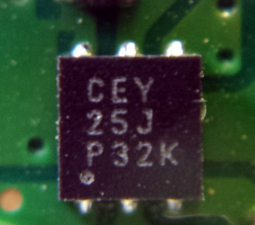
It is switching controller chip for 1.8V WiFi module power supply. This chip goes bad very often on Super slims.
Datasheet is not available, because this chip is custom made for Sony.
The information that I've discovered about this chip:
-Step down switching DC/DC converter with enable input
-Input voltage: 5.5V
-Adjustable output voltage
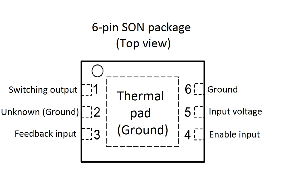
-6-pin SON package with thermal pad
-Pinout:
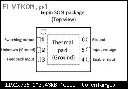
I think it is only option to use any similar chip in the same package and the same pinout. In this case it is necessary to change the inductor value and values of tiny caps and resistors near the chip.
I did it few times and it works without problems.
I used chip TPS62290 (datasheet in the attachment).
The values of inductor and other tiny components are dependent of the chip type. It is described in datasheet of the chip.
Components that should be replaced (values are for the chip TPS62290):
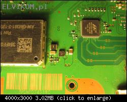
1) Replace with inductor 2.2uH, package: 0806
2) Replace with resistor 360kΩ, 1%, package: 0402
3) Replace with bridge or resistor 0R, package: 0402
4) Replace with capacitor 22pF, package: 0402
5) Replace with resistor 180kΩ, 1%, package: 0402
All components are availabe here:
Chip TPS62290
Inductor 2.2uH
Resistor 0R
Resistor 180kΩ
Resistor 360kΩ
Capacitor 22pF
After replacing all of the described components first power it on without WiFi module and measure the output voltage. If it is ok (1.8V) solder new WIFI module (or replace Marwell QFN chip on the WiFi module, which goes bad) and it should work.
It is switching controller chip for 1.8V WiFi module power supply. This chip goes bad very often on Super slims.
Datasheet is not available, because this chip is custom made for Sony.
The information that I've discovered about this chip:
-Step down switching DC/DC converter with enable input
-Input voltage: 5.5V
-Adjustable output voltage
-6-pin SON package with thermal pad
-Pinout:
I think it is only option to use any similar chip in the same package and the same pinout. In this case it is necessary to change the inductor value and values of tiny caps and resistors near the chip.
I did it few times and it works without problems.
I used chip TPS62290 (datasheet in the attachment).
The values of inductor and other tiny components are dependent of the chip type. It is described in datasheet of the chip.
Components that should be replaced (values are for the chip TPS62290):
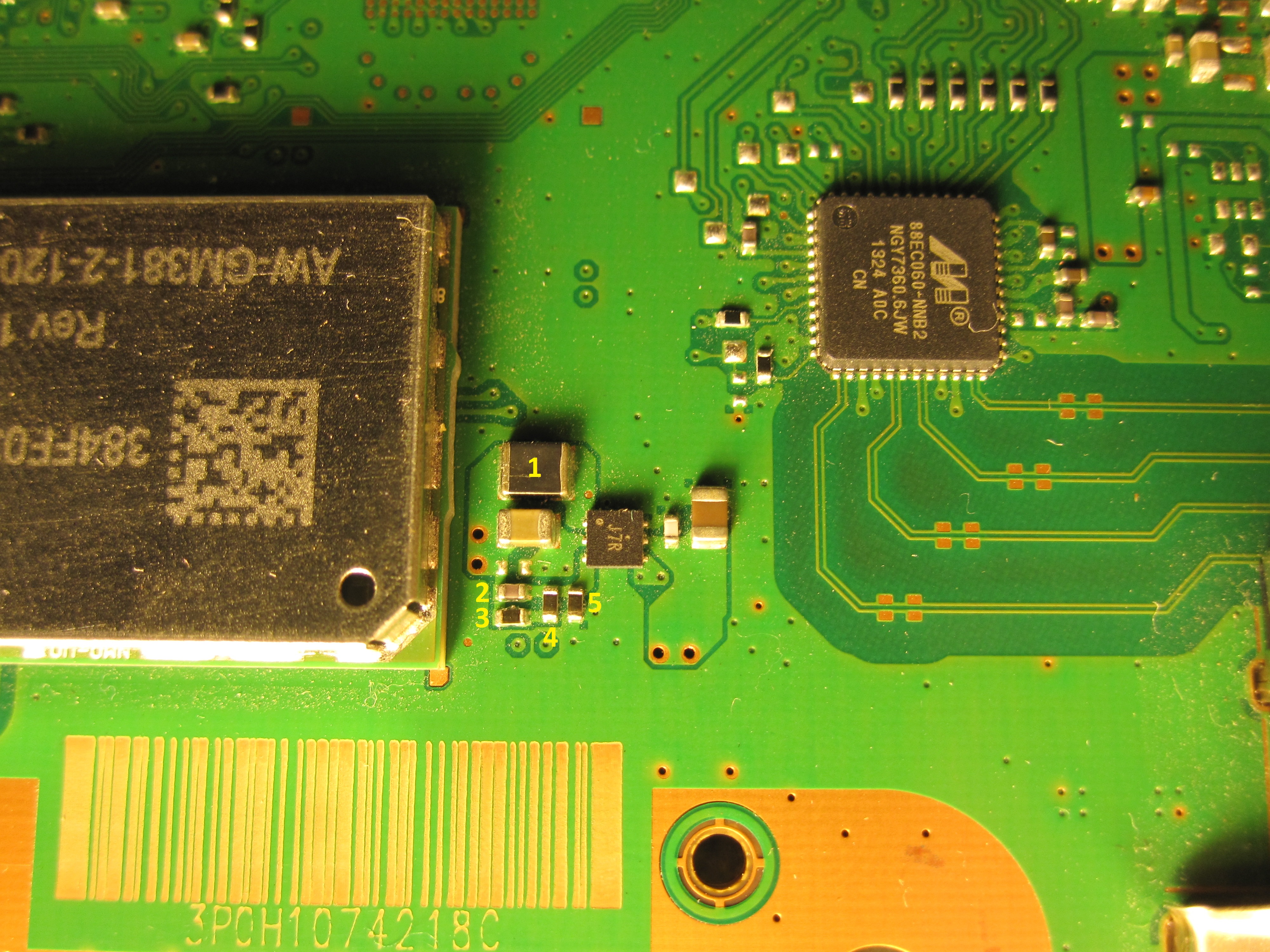
1) Replace with inductor 2.2uH, package: 0806
2) Replace with resistor 360kΩ, 1%, package: 0402
3) Replace with bridge or resistor 0R, package: 0402
4) Replace with capacitor 22pF, package: 0402
5) Replace with resistor 180kΩ, 1%, package: 0402
All components are availabe here:
Chip TPS62290
Inductor 2.2uH
Resistor 0R
Resistor 180kΩ
Resistor 360kΩ
Capacitor 22pF
After replacing all of the described components first power it on without WiFi module and measure the output voltage. If it is ok (1.8V) solder new WIFI module (or replace Marwell QFN chip on the WiFi module, which goes bad) and it should work.
Re: PS3 4004 MSX-001 identyfikacja elementu
Napisal/-a Google Adsense [BOT] • 19 Avgust 2017, 19:05
Ta tema je označena kot ARHIVSKA. Odgovorite samo, če vaše sporočilo vsebuje rešitev (Pravila in Pogoji, 12.1).
| Podobne Teme |
|---|
| XBOX Series X (M1236009-001) - identyfikacja elementu. [REŠENO] |
| PS4 PCB SAC-001 identyfikacja elementów |
| Identyfikacja elementu [REŠENO] |
| Identyfikacja elementu [REŠENO] |
| SVOD 3 identyfikacja elementu. [REŠENO] |
| SVOD4 identyfikacja elementu Q2. |
Kdo je na strani
Po forumu brska: 0 registriranih uporabnikov in 2 gostov
_______________________________Vse pravice pridržane. Nepooblaščeno kopiranje vsebine te spletne strani ali njenega dela je strogo prepovedano.
Vse blagovne znamke, izdelki ali storitve, objavljene na tej spletni strani, pripadajo njihovim zakonitim lastnikom, so avtorsko zaščitene in se uporabljajo samo v informativne namene.