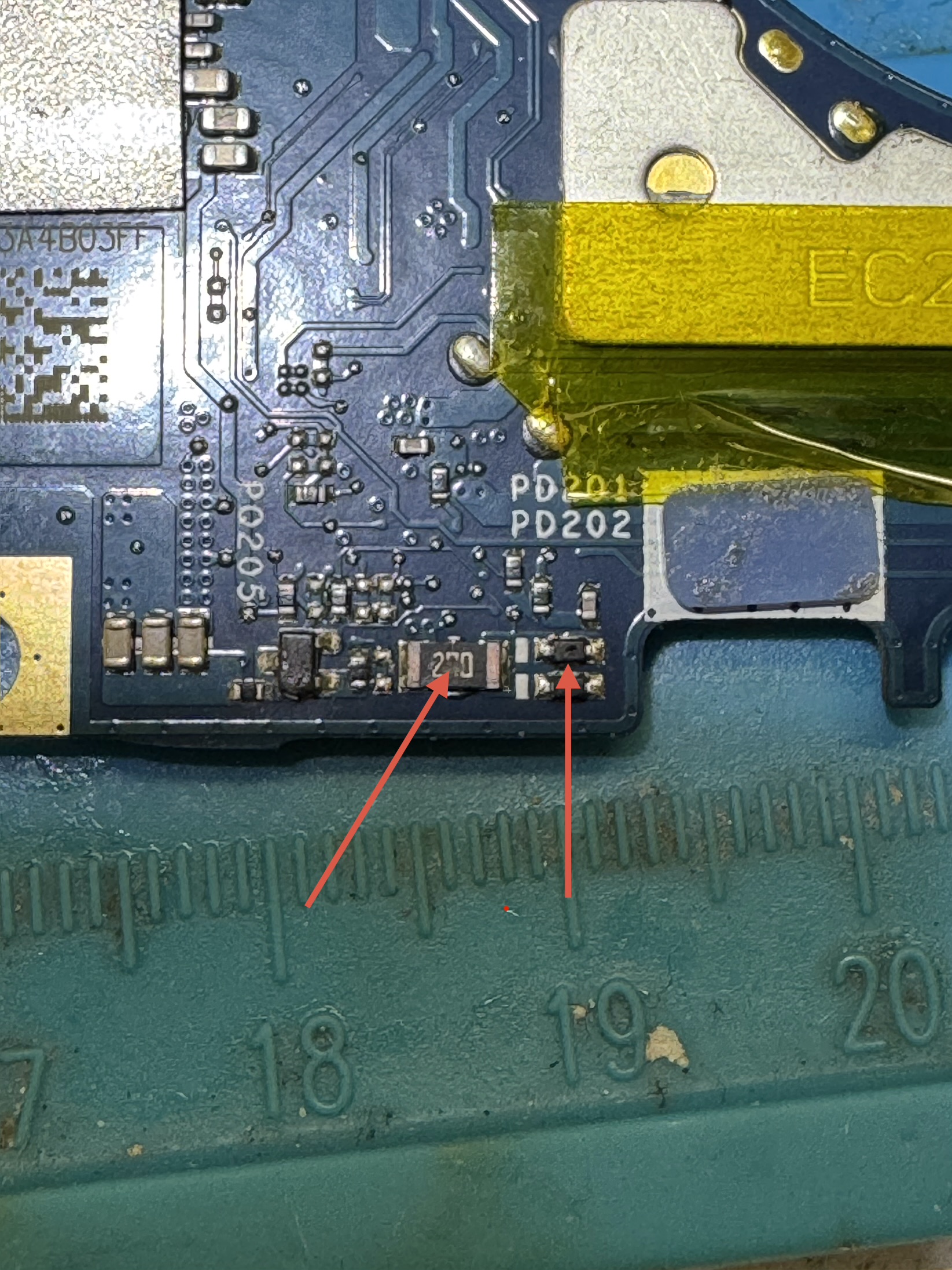
Topic title should contain: the device's manufacturer, full model and the brief description of problem.
Topic message should contain: the PCB marking code (required in case of hardware repairs), an extended description of problem, things you have checked/replaced/measured, your conclusions and the question. If you are not able to find the PCB marking code, please read THIS TOPIC. If you still cannot locate the PCB markings, please upload a clean, both-side photos of the mainboard - it is required to remove any films, modules or brackets possibly covering these markings.
Before posting a new topic please read all topics in TRAININGS subforum and make a preliminary diagnostic based on the content of those trainings.
Uploading of any complete schematics, BIOS / firmware files or any other kind of documentation, or linking to 3rd party websites with such files, is STRICTLY PROHIBITED. You can only upload the small portion of documentation or, link to BIOS file on UNVERIFIED BIOS FILES subforum, which simplifies the diagnostics/repair. You are not allowed to upload more then one complete page of instruction/schematic per single topic. The file you upload must not contain any watermarks, "confidential" markings, links or email addresses and cannot be password-protected.
It is only permitted to describe one faulty device per single topic - you should always open a new topic for each subsequent device.
Requesting of the full schematics, BoardView files, BIOS files or any other kind of documentation is NOT ALLOWED in this subforum. If you need to ask for any of these, you should open a new topic in DOCUMENTATION/BIOS REQUEST subforum.
Connect the power supply to the board via a USB Type-C power meter and specify the voltage and current displayed on the meter. (picture source: ubuy.com):
Measure the voltages to ground on pins 1, 4, 8, 12, 14, 15, 16, 17, 18, 19, 21, 22, 24, 25 of charger chip PU200 with the power supply connected only (without the battery).
valieromarco wrote:PR208 pin 2= 250 ohm (maybe to low)?
Yes, way too low. Remove PC227 and remeasure this resistance to ground. If still low, replace PU200 and PR208 (2Ω). If it goes high after removing PC227, replace PC227 (1uF/25V, 0402 case).
Remeasure the voltages suggested in post #6 and also remeasure the voltage to ground on any pin of resistor PR211 with the power supply connected only.
Now the correct measurement is the last one. Situation has changed when I measured the the last pin and to confirm all voltages I checked it again from 1 pin and I noticed different measures
Measure the resistances to ground on pins 8, 18 of charger chip PU200. If both resistances are high (in the kΩ range or greater), replace the chip PU200.
I replaced PU 200 no power on but I got a new measurement. You can see the message #11 I changed old measure with last correct voltages and are marked as “LAST MEASURE”
I have something wrong: PL 401 = 3,3V should be 5V PL 250 = 3,66V PL 702 = 0V
I removed PL 401 and on PU400 side I have 5V so there is something wrong on other side.
Users browsing this forum: No registered users and 1 guest
_______________________________ All rights reserved. Unauthorised copying of this website's content or any of its part is strictly forbidden. Any trademarks, brand names, products or services published on this website belong to their legal owners, are copyrighted and used for information purposes only.